Axial-axial magnetic field electromagnetic planetary gear power divider
A power divider, axial magnetic field technology, applied in electrical components, electromechanical devices, electric components, etc., can solve the problems of inability to power output, bulky volume, limited performance, etc., and achieve reduced exhaust emissions, small size, and simple structure. Effect
- Summary
- Abstract
- Description
- Claims
- Application Information
AI Technical Summary
Problems solved by technology
Method used
Image
Examples
specific Embodiment approach 1
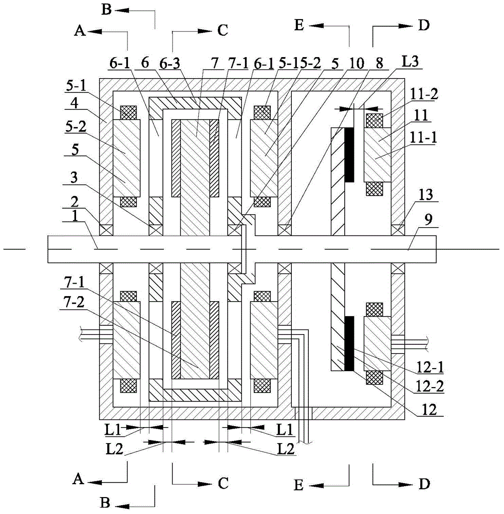
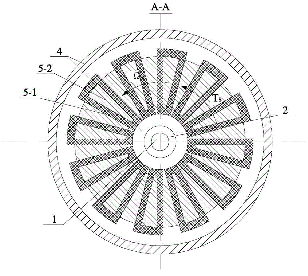
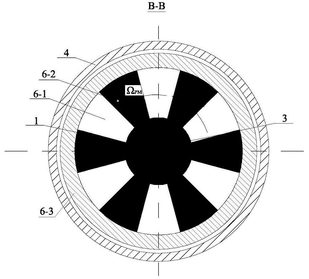
[0050] Specific implementation mode one: the following combination Figure 1 to Figure 8 Describe this embodiment, the axial-axial magnetic field electromagnetic planetary gear power divider described in this embodiment, the housing 4 is divided into left and right parts by a separator, and the axial double-rotor motor and the axial torque adjustment motor are respectively arranged on In the left and right parts of the housing 4, the axial double-rotor motor includes two first stators 5, a first permanent magnet rotor 6, a magnetic modulation rotor 7, a magnetic modulation rotor output shaft 1 and a permanent magnetic rotor output shaft 9 , the axial torque regulating motor includes a second stator 11 and a second permanent magnet rotor 12, the permanent magnet rotor output shaft 9 is also used as the rotor shaft of the axial torque regulating motor,
[0051] The second stator 11 of the axial torque regulating motor is fixed on the inner wall of the right end cover of the hous...
specific Embodiment approach 2
[0059] Specific implementation mode two: the following combination Figure 1 to Figure 6 , Figure 15 to Figure 23 Describe this embodiment, this embodiment will further explain Embodiment 1, the first permanent magnet rotor 6 includes a rotor bracket 6-3, 2n first permanent magnet units 6-1 and 2n second permanent magnet units 6-2, Both end faces of the rotor bracket 6-3 facing the two first stators 5 are provided with n first permanent magnet units 6-1 and n second permanent magnet units 6-2, and n first permanent magnet units 6 -1 and n second permanent magnet units 6-2 are staggered along the circumferential direction, the magnetization directions of the n first permanent magnet units 6-1 are the same, and the magnetization directions of the n second permanent magnet units 6-2 are the same The magnetization directions of the first permanent magnet unit 6-1 and the first permanent magnet unit 6-2 are opposite; the magnetization directions of the first permanent magnet unit...
specific Embodiment approach 3
[0100] Specific implementation mode three: the following combination Figure 7 and Figure 8Describe this embodiment, this embodiment will further explain Embodiment 1, the first permanent magnet rotor 6 includes a rotor bracket 6-3, 2n first permanent magnet units 6-1 and 2n first permanent magnet rotor cores 6-4 , n first permanent magnet units 6-1 and n first permanent magnet rotor cores 6-4 are arranged on both end faces of the rotor bracket 6-3 facing the two first stators 5, and n first permanent magnets The units 6-1 and the n first permanent magnet rotor cores 6-4 are alternately arranged along the circumferential direction, and the magnetization directions of the n first permanent magnet units 6-1 are the same.
[0101] The axial dual-rotor motor in this embodiment saves half of the permanent magnet consumption under the permanent magnet magnetic field with the same number of pole pairs.
PUM
 Abstract
Description
Claims
Application Information
 - Generate Ideas
- Intellectual Property
- Life Sciences
- Materials
- Tech Scout
- Unparalleled Data Quality
- Higher Quality Content
- 60% Fewer Hallucinations
Browse by: Latest US Patents, China's latest patents, Technical Efficacy Thesaurus, Application Domain, Technology Topic, Popular Technical Reports.
© 2025 PatSnap. All rights reserved.Legal|Privacy policy|Modern Slavery Act Transparency Statement|Sitemap|About US| Contact US: help@patsnap.com


