
Tangential injection type whirl flow jet flow grinding drill bit for horizontal well

An injection-type, horizontal well technology, applied in the direction of drill bit, drilling equipment, earthwork drilling and production, etc., can solve the problems that affect the timely cleaning of bottom cuttings, reduce the flow of drilling fluid at the bottom of the well, and reduce the range of jet flushing, etc., to achieve improved Effects of clearing rock efficiency, reducing final settlement velocity, and increasing overflow velocity

Inactive Publication Date: 2015-02-25
CHINA UNIV OF PETROLEUM (BEIJING)
View PDF11 Cites 16 Cited by
  • Summary
  • Abstract
  • Description
  • Claims
  • Application Information

AI Technical Summary

Problems solved by technology

However, due to the diversion effect of the reverse nozzle of the jet mill drill bit, the flow rate of the drilling fluid at the bottom of the well is reduced, so the number of water holes of the drill bit at the bottom of the well is reduced, and the range of jet flushing is also significantly reduced
Although the high-concentration turbulent sand pumping device of the jet mill bit can reduce the pressure difference at the bottom of the hole and suck cuttings, but due to the small range of jet flushing, it will affect the timely cleaning of cuttings at the bottom of the well, resulting in repeated crushing of some cuttings. Affect rock breaking efficiency

Method used


Image

  • Tangential injection type whirl flow jet flow grinding drill bit for horizontal well
  • Tangential injection type whirl flow jet flow grinding drill bit for horizontal well
  • Tangential injection type whirl flow jet flow grinding drill bit for horizontal well

Examples


Embodiment Construction

[0024] Below in conjunction with accompanying drawing, illustrate the specific embodiment that the present invention proposes, structure, feature and effect thereof, detailed description is as follows:

[0025] The horizontal well tangential injection swirling jet mill drill bit includes a PDC drill bit 1, a tangential injection swirling jet sand washing device 2, a high-concentration turbulent sand pumping device 3, and a jet crushing device 4.

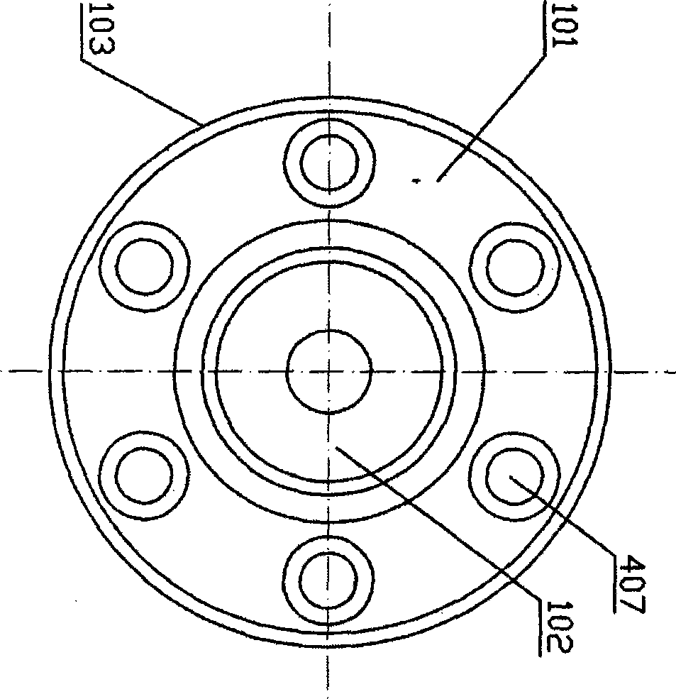
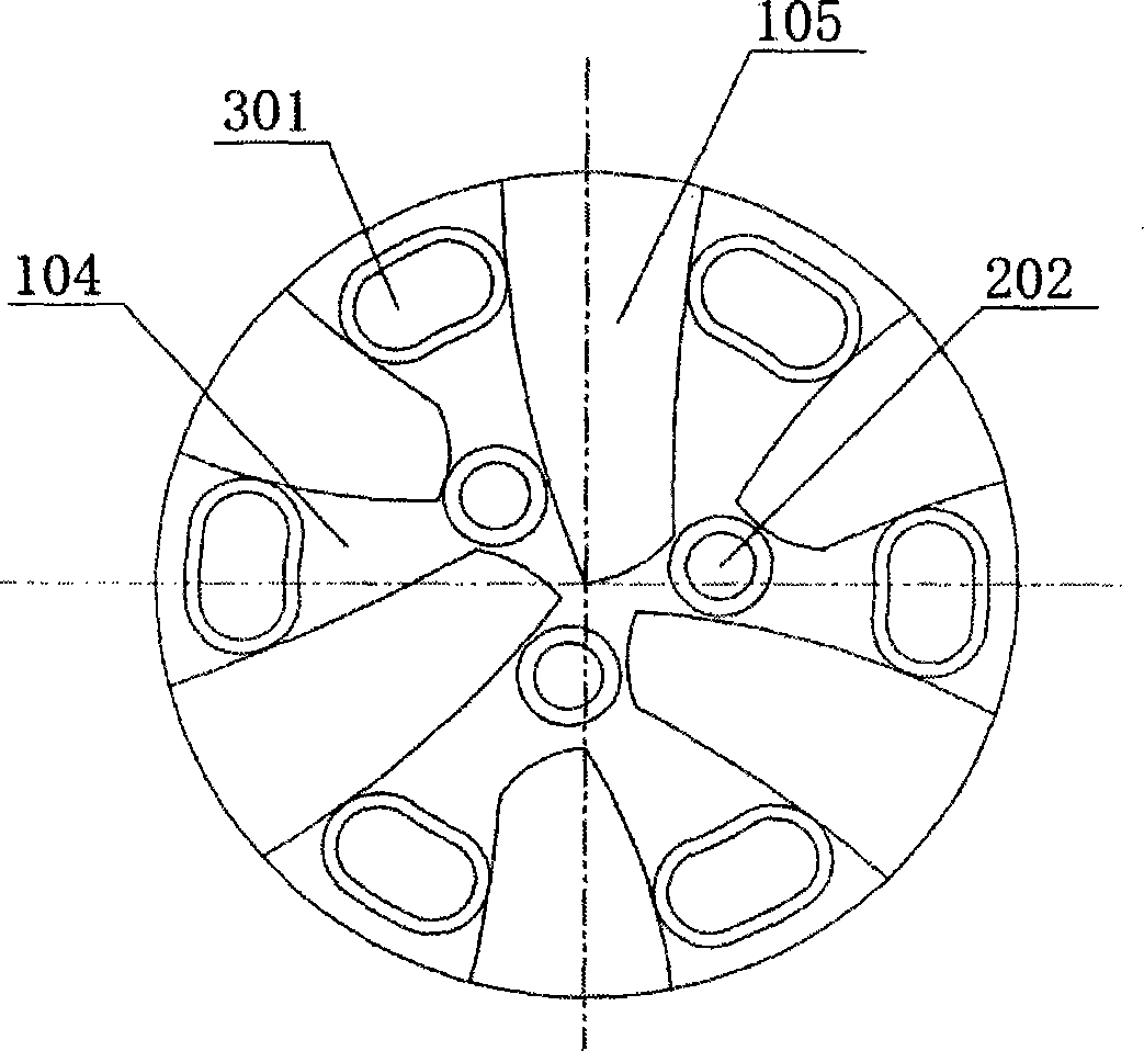
[0026] The PDC drill bit includes a drill bit body 101, a main flow channel 102, a gauge 103, a chip removal groove 104 at the end of the drill bit, and a PDC blade 105; the PDC blade 105 is the working part of the horizontal well tangential injection swirl jet mill drill bit for cutting rocks, The surface is covered with PDC cutting teeth; the chip flute 104 at the end of the drill bit is arranged between the PDC blades 105;

[0027] The tangential injection type rotary jet sand washing device 2 includes a bottom hole debris stirrin...


PUM


Abstract

The invention discloses a tangential injection type whirl flow jet flow grinding drill bit for a horizontal well. The grinding drill bit mainly comprises a PDC drill bit body and is characterized in that a debris discharging groove in the gauge protection portion of the PDC drill bit body is omitted, and the PDC drill bit body is internally and additionally provided with a tangential injection type rotating jet flow sand washing device, a high-concentration turbulence sand pumping device and a jet flow smashing device. According to the tangential injection type rotating jet flow sand washing device, high-speed rotation jet flow is generated through tangential injection type rotating jet flow spray nozzles, a well bottom whirl flow field beneficial to rock debris cleaning is formed, the stress condition of well bottom rock debris is improved, and the well bottom rock debris cleaning efficiency is improved. The high-concentration turbulence sand pumping device pumps and sucks the well bottom fluid based on the principle of a sand pumping pump, the well bottom pressure difference is reduced, unbalance is achieved, and the mechanical drilling speed is increased. The jet flow smashing device effectively smashes the rock debris based on the principle of a jet mill, the rock debris carrying efficiency is improved, the rock debris bed in the horizontal well is eliminated radically, and safe and efficient drilling of the horizontal well is finally achieved.

Description

technical field [0001] The invention belongs to the field of drilling and oil and gas engineering, in particular to a horizontal well tangential injection type swirl jet mill drill bit. Background technique [0002] As we all know, rock carrying is an important problem in drilling horizontal wells and extended reach wells. If the cuttings carrying effect cannot meet the requirements, it will lead to many problems, such as high friction and high torque, sand settling, pipe sticking, casing running and Difficulty in cementing, severe wear of drilling tools, difficulty in running logging instruments, etc., may even lead to suspension of drilling operations. However, the jet mill bit for safe and efficient mud drilling for horizontal wells (CN201310654747.4) and the jet mill bit for safe and efficient gas drilling for horizontal wells (CN201310654718.8) recently developed by China University of Petroleum (Beijing) can not only reduce the bottom hole pressure difference, To incr...

Claims


Application Information

Patent Timeline
Patent Type & Authority Applications(China)
IPC IPC(8): E21B10/60E21B7/18E21B21/00
CPCE21B7/18E21B10/602E21B21/00E21B21/085
Inventor 高德利陈绪跃郭柏云
Owner CHINA UNIV OF PETROLEUM (BEIJING)
Learn More