
Safe multifunctional food processor

A multi-functional, cooking machine technology, applied in the field of food cooking machines, can solve the problems of high noise, complex structure and operation, high rotation speed, and achieve the effects of compact structure, double protection of machinery and circuits, and simple structure

Active Publication Date: 2015-02-25
GUANGDONG KEJIALIN ELECTRICAL APPLIANCE MFG
View PDF6 Cites 3 Cited by
  • Summary
  • Abstract
  • Description
  • Claims
  • Application Information

AI Technical Summary

Problems solved by technology

[0002] At present, cooking machines on the market can generally be used in conjunction with a variety of mixers, such as egg beaters, dough sticks or mixing knives, meat mincing knives, etc., and only one of them can be used when working, so in When using one of the stirring functions, a protection device (mechanical protection or circuit protection) will be used to lock the other stirring function, but the structure is complicated to operate
Moreover, the motor speed (up to 25,000 r / min) required for egg beaters and dough sticks is relatively high, while the speed required for mixing knives and mincing knives (up to 16,000 r / min) is relatively high. Low, the existing structure does not have a special speed reduction structure to reduce the speed of the mixing knife and the minced meat knife. When using the inserted mixing knife and the minced meat knife to work, the motor can reach 25,000 rpm, the speed is too high, and the noise is too high Large, which seriously affects consumers' use of stirring and mincing functions

Method used


Image

  • Safe multifunctional food processor
  • Safe multifunctional food processor
  • Safe multifunctional food processor

Examples


Embodiment Construction

[0036] The present invention will be further described below in conjunction with the accompanying drawings and embodiments.

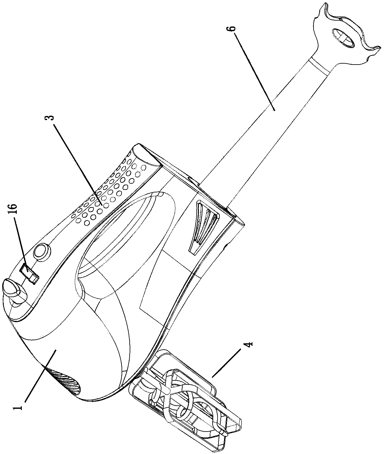
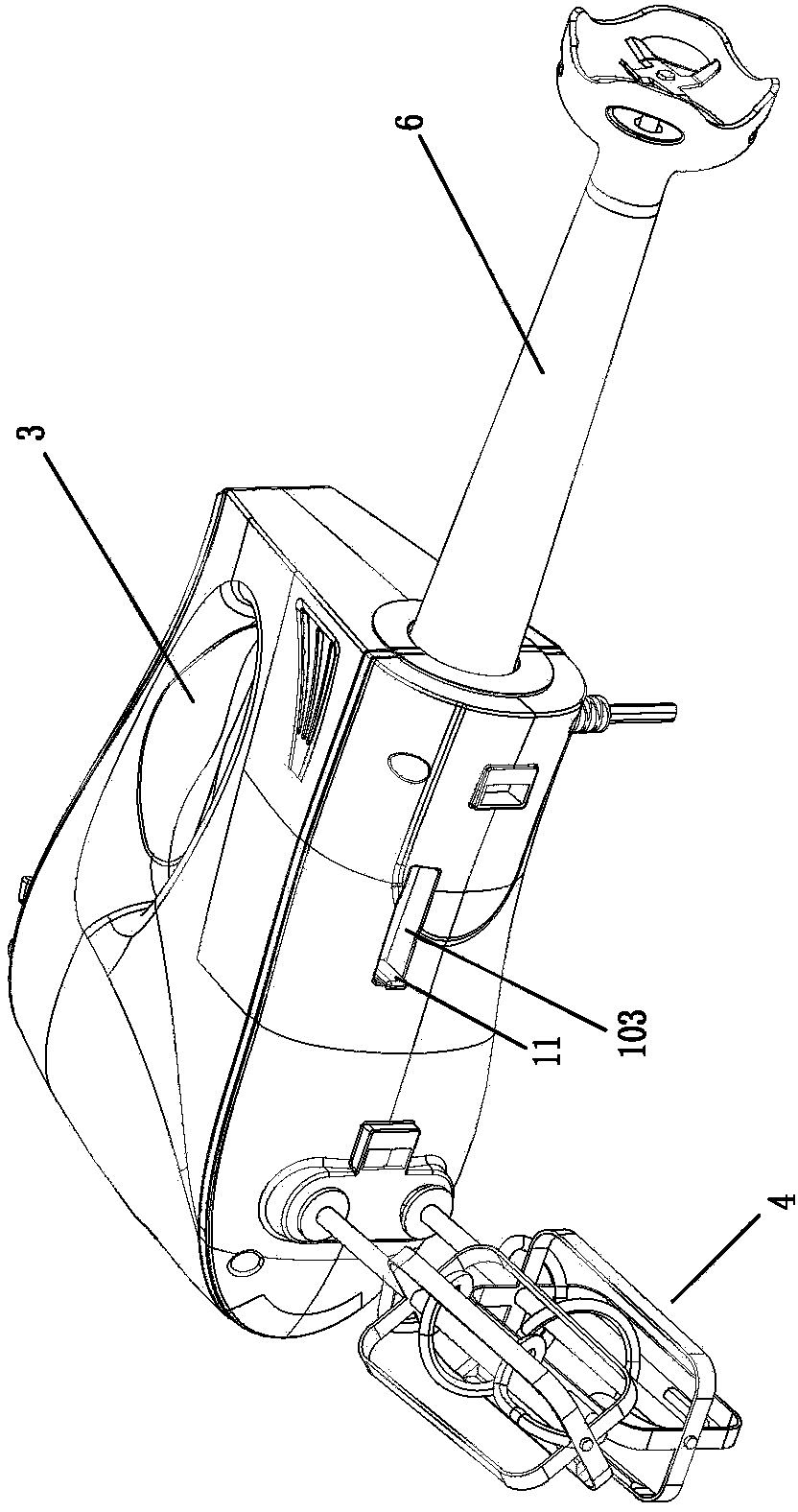
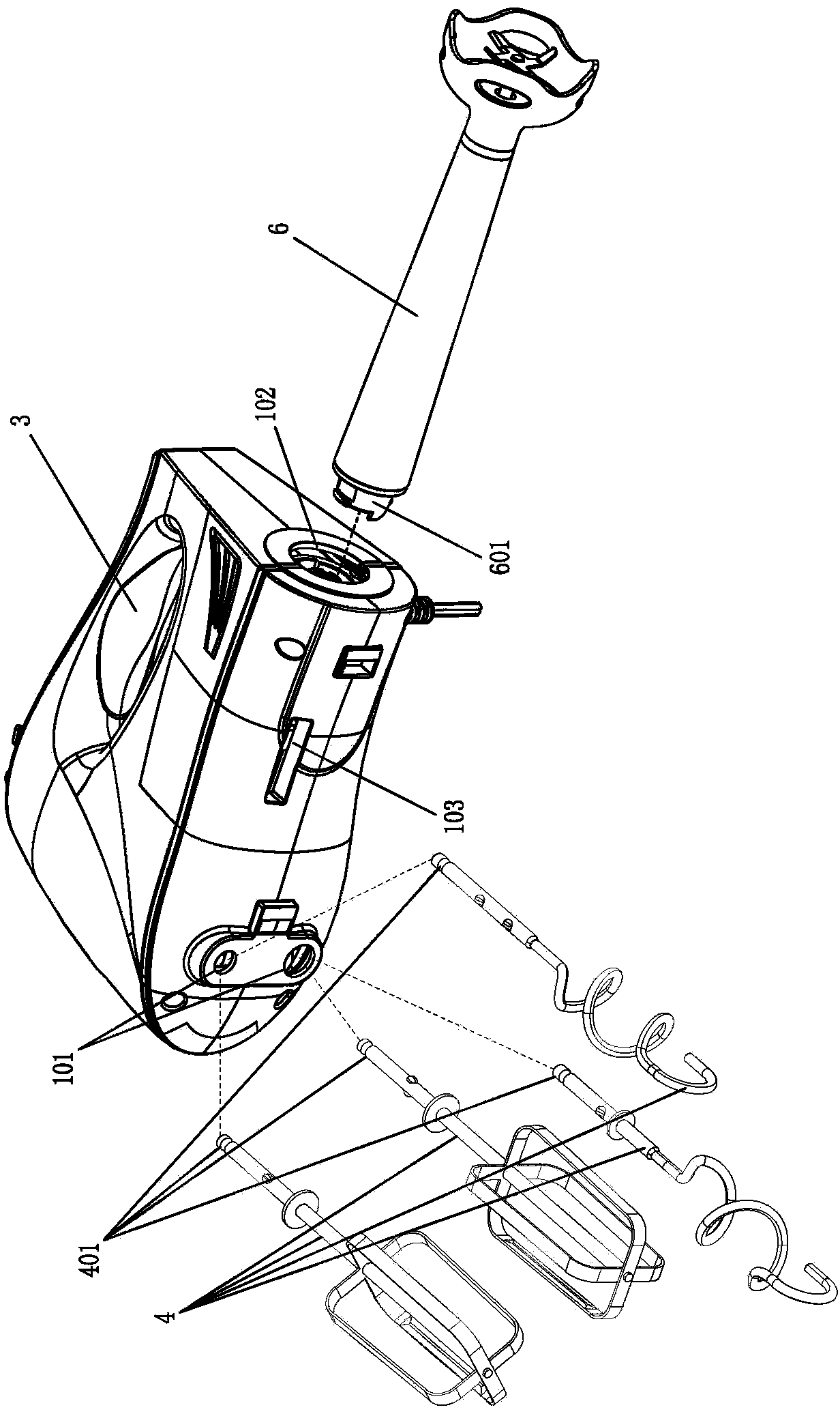
[0037] Such as Figure 1 to Figure 10 As shown, a safe multifunctional cooking machine includes a casing 1, a motor 2 is installed in the casing 1, a hand grip 3 is provided on the top of the casing 1, and a bottom end of the casing 1 located below the grip 3 is opened. There is a first power output hole 101 suitable for the cooperation of the first agitator 4, and the first power connection mechanism 5 connected with the motor 2 is installed inside the first power output hole 101, and the connection end 401 of the first agitator 4 passes through The first power output hole 101 is installed and matched with the first power connection mechanism 5, and the side end of the casing 1 located on the side of the hand grip 3 is provided with a second power output hole 102 suitable for the connection end 601 of the second agitator 6. A second power connection mec...


PUM


Abstract

The invention relates to a safe multifunctional food processor. A handheld part is arranged at the top end of a machine case, a first power output hole suitable for being matched with a first stirrer is formed in the bottom end of the portion, located below the handheld part, of the machine case, a first baffle is arranged in the portion, between a first power connecting mechanism and the first power output hole, of the machine case, a second baffle is arranged in the portion, between a second power connecting mechanism and a second power output hole, of the machine case, the second baffle is in linkage with the first baffle through a connecting belt, a shifting block is arranged at the bottom end of the portion, extending out of the machine case, of the connecting belt, a shifting block limiting groove is formed in the bottom end, corresponding to the shifting block, of the machine case, and the shifting block is shifted from one end of the limiting groove to the other end of the limiting groove so that the connecting belt can drive the first baffle and the second baffle to achieve linkage and the first power output hole and the second power output hole can be selectively opened or closed; linkage interlocking between the two power output holes can be achieved, a stirring cutter and a meat smashing cutter are used for automatically decreasing the rotating speed, the safe multifunctional food processor is more reliable for the safety of a customer, and noise is effectively lowered.

Description

technical field [0001] The invention relates to the technical field of a food cooking machine, in particular to a cooking machine that realizes double protection and speed reduction through mechanical protection, circuit protection and automatic speed reduction, and has the functions of safety, reliability and low noise. Background technique [0002] At present, cooking machines on the market can generally be used in conjunction with a variety of mixers, such as egg beaters, dough sticks or mixing knives, meat mincing knives, etc., and only one of them can be used when working, so in When using one of the stirring functions, a protection device (mechanical protection or circuit protection) will be used to lock the other stirring function, but the structure is complicated to operate. Moreover, the motor speed (up to 25,000 r / min) required for egg beaters and dough sticks is relatively high, while the speed required for mixing knives and mincing knives (up to 16,000 r / min) is ...

Claims


Application Information

Patent Timeline
IPC IPC(8): A47J44/02
Inventor 陈明开
Owner GUANGDONG KEJIALIN ELECTRICAL APPLIANCE MFG
Learn More