
Track slide type pressure relief switch

A slide-type, trajectory technology, used in wellbore/well components, earthmoving, sealing/packing, etc., can solve the problems of construction failure, easy upward movement of tubing, etc., achieve unique trajectory design, avoid radial The effect of exposed vias

Inactive Publication Date: 2016-11-09
张晓义
View PDF8 Cites 0 Cited by
  • Summary
  • Abstract
  • Description
  • Claims
  • Application Information

AI Technical Summary

Problems solved by technology

[0002] Oil well casing deformation (hereinafter referred to as casing deformation) is a practical problem often encountered in oil wells. At present, in the construction process of a new hydraulic shaping and repairing casing deformation well technology, it is necessary to neutralize the casing deformation equipment and the high-pressure hydraulic medium in the tubing. Drain, the pressure relief switch is a key part of the complete set of equipment. During the workover process, the equipment below the pressure relief switch is relatively fixed with the oil well casing. The upper part of the pressure relief switch is connected with the tubing string, and the tubing string When there is a high-pressure liquid inside, the high-pressure liquid has a relatively large upward thrust on the tubing string. When the oil well is shallow, the weight of the tubing is lighter, which makes the tubing easy to move upwards, resulting in construction failure.

Method used


Image

  • Track slide type pressure relief switch
  • Track slide type pressure relief switch
  • Track slide type pressure relief switch

Examples


Embodiment Construction

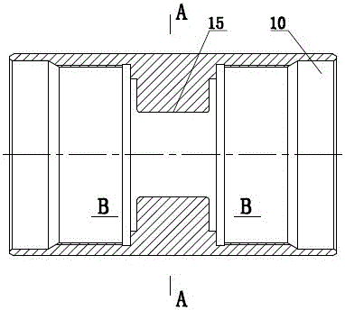
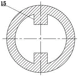
[0027] As shown in the figure, the track slideway pressure relief switch includes an outer sleeve 2 and a track core tube 3 arranged in the outer sleeve 2. The number of the outer sleeves 2 is two, and a slide is used between the two outer sleeves 2 The column collar 4 is connected and fixed, the upper end of the upper outer casing 2 is threaded with the upper joint 1, the lower end of the lower outer casing 2 is threaded with the lower collar 6, and the track core pipe 3 is composed of the upper thick-diameter cylindrical section 13 and the lower Small-diameter cylindrical section 14 is composed of an axial through hole 11 in the middle, and a plurality of radial through-holes 12 communicating with the axial through-hole 11 are provided on the lower thin-diameter cylindrical section 14. The lower end of the section 14 protrudes to the outside of the lower collar 6 and an annular seal 5 is arranged between the inner ring groove of the lower collar 6 and the lower thin-diameter ...


PUM


Abstract

The invention relates to a track slide type pressure relief switch, which comprises two outer sleeves and a track core tube arranged in the outer sleeves. The two outer sleeves are connected and fixed by a slide column coupling. Composed of a cylindrical section and a lower thin-diameter cylindrical section, the lower thin-diameter cylindrical section is provided with a radial through hole communicating with its axial through hole, and the upper thick-diameter cylindrical section corresponds to the inner convex slider on the inner wall of the slide column coupling. Groove, the upper groove of the track groove is composed of two groups of grooves evenly distributed, each group of grooves has a long straight groove and a short straight groove, and the adjacent long straight grooves and short straight grooves are separated by the same The inclined plane Ⅰ connects and transitions in the same direction, and the lower groove is composed of four lower straight grooves evenly distributed, and the adjacent lower straight grooves are respectively connected and transitioned by the inclined plane Ⅱ in the same direction. . It prevents the upward string movement of the tubing string in the process of shaping and repairing the casing and changing the well, so as to ensure the smooth progress of the construction process and reliable performance.

Description

technical field [0001] The invention belongs to a pressure relief switch for high-pressure liquid in an oil well tubing string, in particular to a track slideway type pressure relief switch, which is a key device used for oil well shrinkage deformation forming tool sets. technical background [0002] Oil well casing deformation (hereinafter referred to as casing deformation) is a practical problem often encountered in oil wells. At present, in the construction process of a new hydraulic shaping and repairing casing deformation well technology, it is necessary to neutralize the casing deformation equipment and the high-pressure hydraulic medium in the tubing. Drain, the pressure relief switch is a key part of the complete set of equipment. During the workover process, the equipment below the pressure relief switch is relatively fixed with the oil well casing. The upper part of the pressure relief switch is connected with the tubing string, and the tubing string When there is ...

Claims


Application Information

Patent Timeline
Patent Type & Authority Patents(China)
IPC IPC(8): E21B34/12E21B29/10
CPCE21B29/10E21B34/12
Inventor 张晓义
Owner 张晓义
Learn More