Device and method for hoisting round mold of vulcanization tank

A hoisting device and vulcanization tank technology, which is applied in the direction of transportation and packaging, load hanging components, trolley cranes, etc., can solve problems such as waste of space, unsafe and reliable, and safety production accidents, and achieve a compact overall structure and improve production efficiency , Reliable hoisting effect

Active Publication Date: 2016-10-05
福建省三明市东辰机械制造有限责任公司
View PDF9 Cites 0 Cited by
  • Summary
  • Abstract
  • Description
  • Claims
  • Application Information

AI Technical Summary

Problems solved by technology

[0002] When vulcanization tanks are used to produce tapes and other products, workers need to manually lift the round mold into and out of the vulcanization tank, which is not only cumbersome, inefficient, but also unsafe and reliable
For this reason, the Chinese utility model patent CN 203187314 U discloses a vulcanization tank hoisting device, although the automatic and safe hoisting of the belt is realized, but there are the following disadvantages: (1) the end effector needs to be realized by adjusting the cart and trolley Pause at the designated working position, so the operation is troublesome, which affects the production efficiency; (2) The end actuator is driven by an electromagnetic chuck. When the power is suddenly cut off, the electromagnetic chuck loses its function, and safety production accidents will occur, and the hoisting is unreliable; ( 3) Since the guide column is telescopic, the lifting stroke of the end effector can only be half of the length of the guide column extended to the maximum value. Therefore, for a vulcanization tank of the same height, a higher frame is required, which wastes space. The overall structure is not compact

Method used


Image

  • Device and method for hoisting round mold of vulcanization tank
  • Device and method for hoisting round mold of vulcanization tank
  • Device and method for hoisting round mold of vulcanization tank

Examples


Embodiment Construction

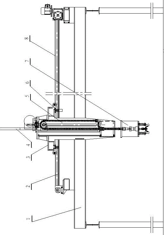
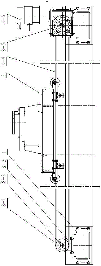
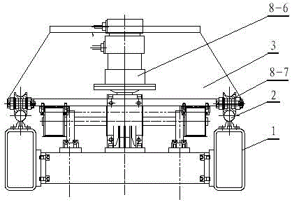
[0027] Such as figure 1 As shown, a vulcanization tank round mold lifting device includes a frame 1, a trolley 3 and an end effector 7. Two guide rails 2 for sliding the trolley 3 are provided on the beam of the frame 1, and the bottom of the trolley 3 is provided with Four pulleys 8-7 that cooperate with the corresponding guide rails 2 respectively, the frame 1 is provided with a traveling mechanism 8 that drives the trolley 3 to move horizontally along the guide rail 2, and the frame 1 is provided with a mechanism that enables the trolley 3 to stop at the corresponding production station The positioning device 6, the trolley 3 is provided with a lifting mechanism 5 that drives the end effector 7 below it to move up and down, and the lifting mechanism 5 is provided with a guide mechanism 4 that guides the end effector 7 to go up and down. 4 adopts a non-telescopic structure, and the end effector 7 is driven by an electric or pneumatic device.

[0028] In this example, if F...


PUM


Abstract

The invention relates to a vulcanizer's round mould hoisting device and a method thereof. The device comprises a framework, a dolly and an end effector. Two guide rails for sliding of the dolly are arranged on a crossbeam of the framework. The bottom of the dolly is provided with four pulleys which respectively match corresponding guide rails. The framework is equipped with a travelling mechanism for driving the dolly to horizontally move along the guide rails. The framework is also provided with a locating device for stopping the dolly at a corresponding production station. The dolly is provided with a lifting mechanism for driving the end effector below the dolly to move up and down. The lifting mechanism is provided with a guide mechanism for guiding lifting of the end effector. The guide mechanism adopts a non-retractable structure. The end effector is driven by an electric or pneumatic device. The device only moves transversely. It is guaranteed that the end effector can stop at a specified working position accurately. It is more convenient to operate the device. Production efficiency is raised. Meanwhile, the end effector is driven by the electric or pneumatic device. Even if in case of sudden power outage, the current working condition can be maintained.

Description

technical field [0001] The invention relates to a hoisting device and method for a round mold of a vulcanization tank. Background technique [0002] When a vulcanization tank is used to produce products such as tapes, workers are required to manually lift the round mold into and out of the vulcanization tank, which is not only troublesome and inefficient, but also unsafe and reliable. For this reason, the Chinese utility model patent CN 203187314 U discloses a vulcanization tank hoisting device, although the automatic and safe hoisting of the belt is realized, but there are the following disadvantages: (1) the end effector needs to be realized by adjusting the cart and trolley Pause at the designated working position, so the operation is troublesome, which affects the production efficiency; (2) The end actuator is driven by an electromagnetic chuck. When the power is suddenly cut off, the electromagnetic chuck loses its function, and safety production accidents will occur, a...

Claims


Application Information

Patent Timeline
Patent Type & Authority Patents(China)
IPC IPC(8): B66C19/00B66C9/00B66C11/00B66C1/10B66C3/14B29C35/00
CPCB29C35/00B66C1/10B66C3/14B66C9/00B66C11/00B66C19/00
Inventor 陈洪朱开华姜发盛张前进陈美娇韩少敏
Owner 福建省三明市东辰机械制造有限责任公司
Why Eureka
Try Eureka