
P-band high-power amplifier device

A high-power amplifier technology, which is applied in the field of P-band high-power amplifier devices and power amplifier devices, can solve the problems of difficult application of burst communication, difficult application of small-sized chassis, and large volume of high-power amplifiers, etc., to achieve improved The effect of transmitting power, shortening maintenance time, and fast switching speed

Active Publication Date: 2015-02-11
NO 54 INST OF CHINA ELECTRONICS SCI & TECH GRP
View PDF7 Cites 5 Cited by
  • Summary
  • Abstract
  • Description
  • Claims
  • Application Information

AI Technical Summary

Problems solved by technology

[0002] At present, there are many power amplifiers in the P frequency band, but there is a big gap in their switching speed, isolation between transceivers and the shutdown depth of power amplifiers, and it is difficult to apply them in burst communication and realize half-duplex communication. Way
From the perspective of volume, generally high-power amplifiers are relatively large in volume, and it is difficult to apply them to small-volume chassis.

Method used


Image

  • P-band high-power amplifier device
  • P-band high-power amplifier device
  • P-band high-power amplifier device

Examples


Embodiment Construction

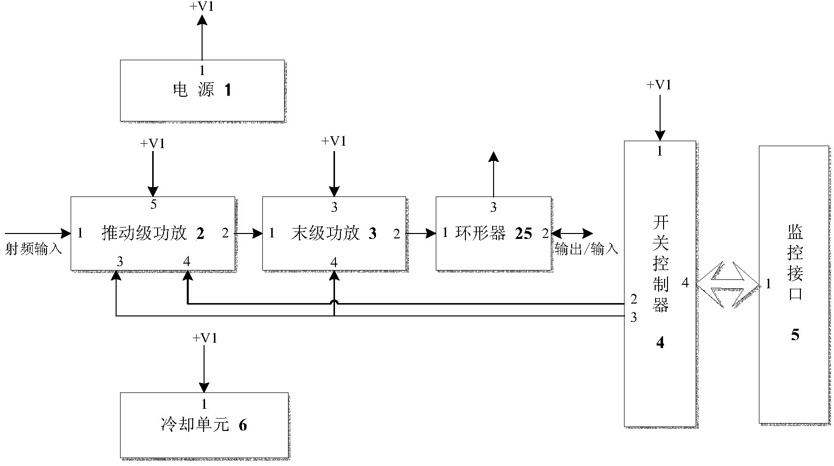
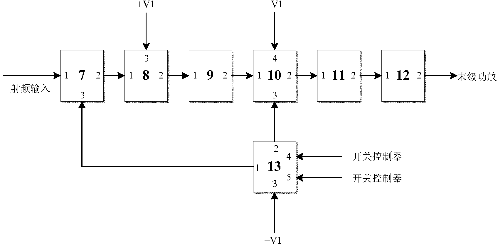
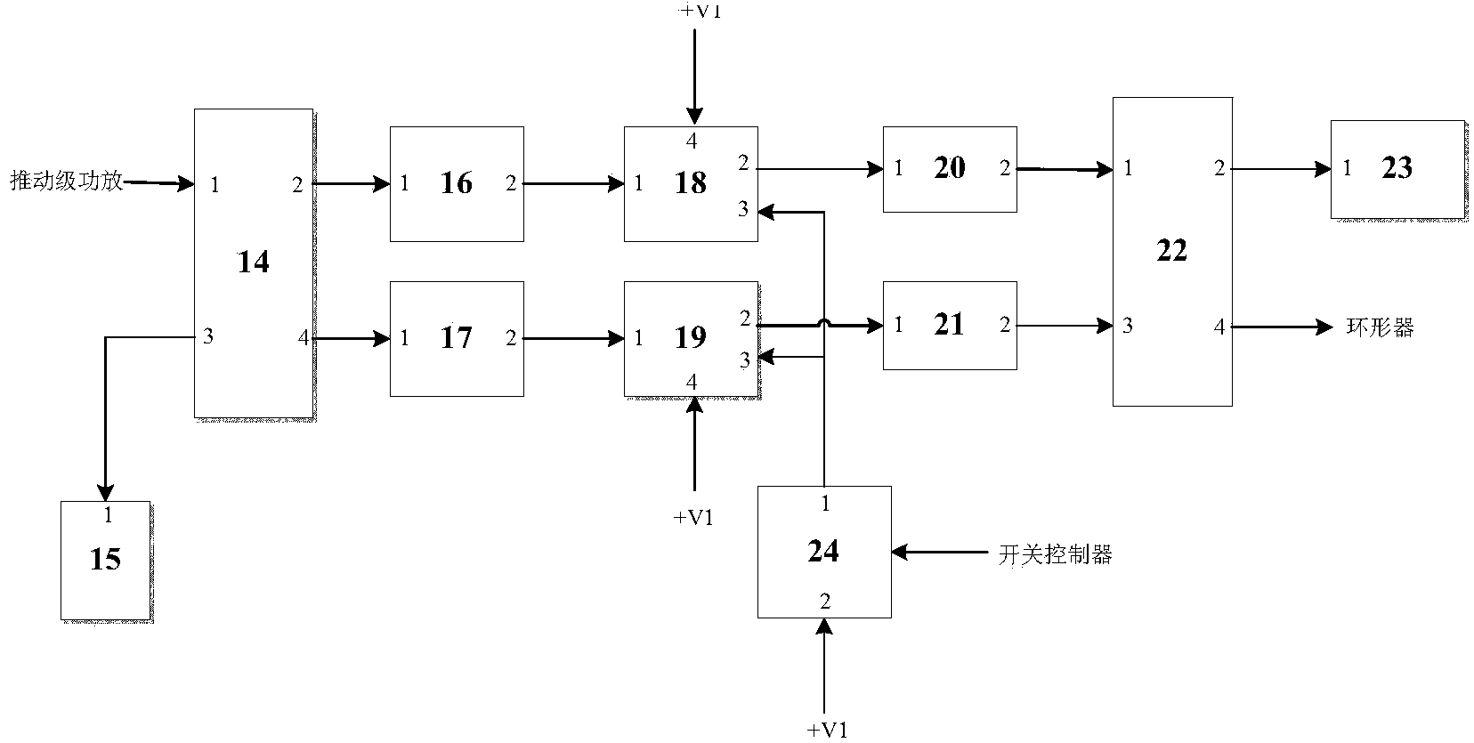
[0014] refer to Figure 1 to Figure 3 , the present invention is composed of a power supply 1, a driving stage power amplifier 2, a final stage power amplifier 3, a switch controller 4, a monitoring interface 5, a cooling unit 6 and a circulator 25. figure 1 It is an electric principle block diagram of the present invention, and the embodiment is according to figure 1 Connect the lines. Among them, the power supply 1 is made of a commercially available integrated regulated DC power supply module, and its output +V1 voltage is +28V. The circulator 25 is made of commercially available general components, and has the functions of performing impedance matching on output signals, providing reflected power detection channels, and providing receiving loop channels. The switch controller 4 completes the switching function for the push stage power amplifier 2 and the final stage power amplifier 3 . The monitoring interface 5 cooperates with the power amplifier to complete functions ...


PUM


Abstract

The invention discloses a P-band high power amplifier device, and relates to a power amplifier device of a P-band signal channel portion in the communication field. The P-band high-power amplifier comprises a propelling-stage power amplifier, a last-stage power amplifier, a switch controller, a power supply, a cooling unit, a monitoring interface and a circulator. In the P-band high power amplifier device, a modularization technology, an integration technology, a thermal design technology and a transmission line transformer technology are adopted to finish high-power synthesis, and the size is relatively small. The P-band high power amplifier has the functions of low-power protection, thermal protection and reflecting protection; the P-band high power amplifier device further has a rapid switching function and a very large switch-off depth, and is particularly suitable to be taken as a power amplifier device in a P-band half-duplex communication system.

Description

technical field [0001] The present invention relates to a P-band high-power amplifier device in the communication field, and is especially suitable as a power amplifier device in a high-power burst communication system. Background technique [0002] At present, there are many power amplifiers in the P frequency band, but there is a large gap in their switching speed, isolation between transceivers and the shutdown depth of power amplifiers, and it is difficult to apply them in burst communication and realize half-duplex communication. Way. In terms of volume, generally high-power amplifiers are relatively large, and it is difficult to apply them to small-volume chassis. Contents of the invention [0003] The object of the present invention is to avoid the disadvantages of the above-mentioned background technology, and provide a high-power amplifier device with fast switching speed, high transceiver isolation, large power amplifier shutdown depth, small volume and high pow...

Claims


Application Information

Patent Timeline
Patent Type & Authority Applications(China)
IPC IPC(8): H03F3/20
CPCH03F3/20
Inventor 李志强高建忠符瑞娇
Owner NO 54 INST OF CHINA ELECTRONICS SCI & TECH GRP
Learn More