Heat exchanger

A heat exchanger and header technology, applied in heat exchange equipment, evaporator/condenser, lighting and heating equipment, etc., can solve the problems of processing cost limitation, uneven secondary distribution, small inertia effect, etc., to achieve Improve flow uniformity and eliminate inertia effect

Active Publication Date: 2015-02-11
ZHEJIANG DUNAN THERMAL SCI & TECH
View PDF8 Cites 3 Cited by
  • Summary
  • Abstract
  • Description
  • Claims
  • Application Information

AI Technical Summary

Problems solved by technology

[0002] like figure 1 As shown, in the U.S. patent application with the publication number US_20100089559_A1, a method of inserting a distribution pipe in the header is disclosed to solve the problem of refrigerant distribution. However, due to the inertia of the refrigerant flow, the flow rate of several small holes near the inlet side will be affected by the backward flow inertia of the refrigerant and will be smaller than the flow rate of the subsequent small holes. The smaller the pipe diameter, the greater the flow rate, so The greater the impact of inertia, and the limitation of processing costs, the number of small holes on the distribution pipe is limited, and it is difficult for the refrigerant to flow into each flat pipe evenly after flowing out of the small holes, and there is a problem of uneven secondary distribution.
In the Chinese patent document with the application number CN200910002438.2, it is disclosed that a porous plate is inserted into the collecting pipe to separate the collecting pipe into upper and lower cavities, such as figure 2 As shown, due to the large volume of the cavity under the header, the refrigerant flow rate is low and the inertial effect is small, but the flow rate at the inlet is relatively high, so the refrigerant flow rate at the small hole near the inlet is small, and the porous plate The small holes are facing the flat tube, and because of the limited number of small holes, there is also the problem of uneven secondary liquid separation after the refrigerant flows out of the perforated plate

Method used


Image

  • Heat exchanger
  • Heat exchanger
  • Heat exchanger

Examples


Embodiment 1

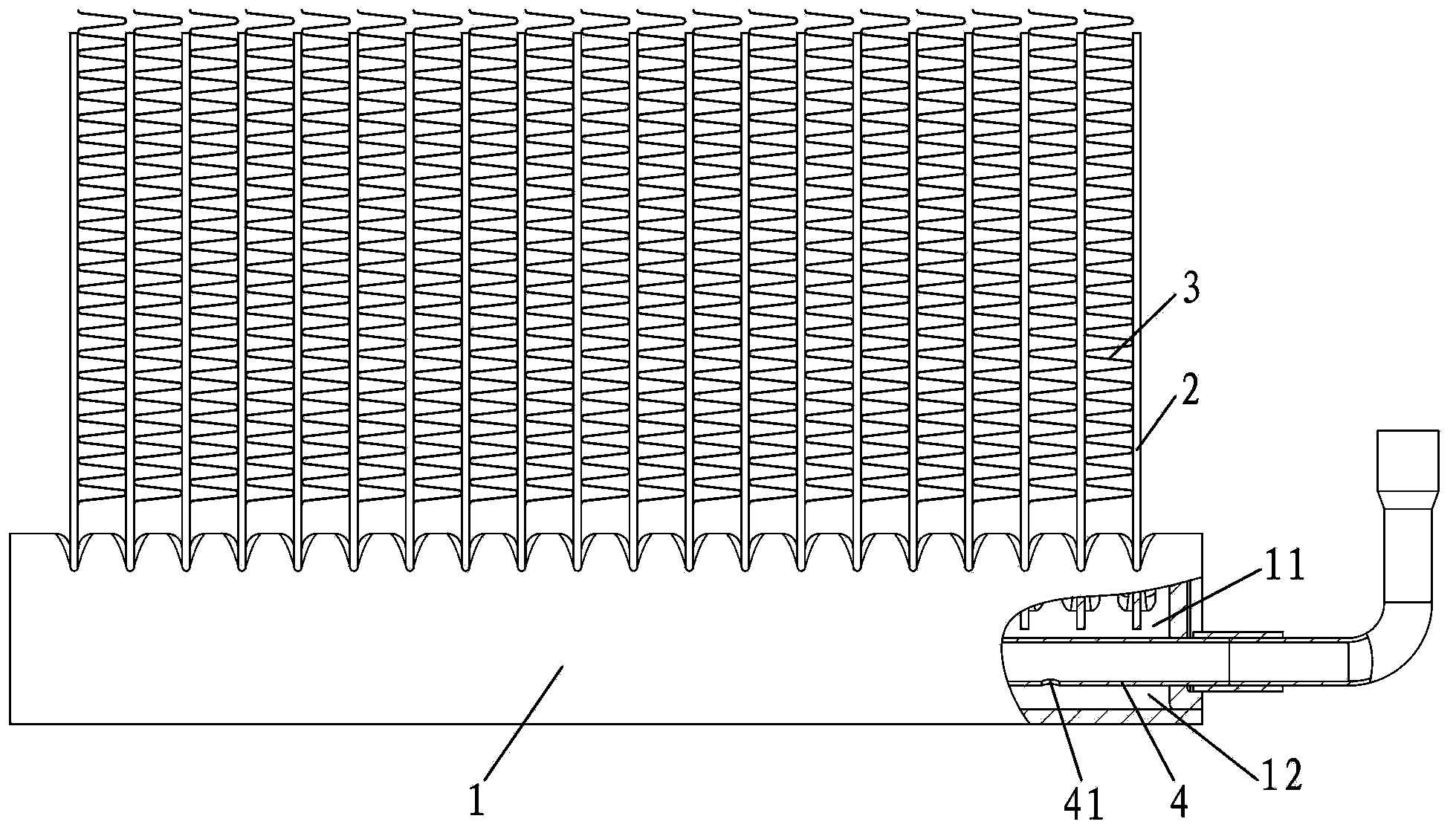
[0034] Reference Figure 3 to Figure 5 , Is a heat exchanger of the present invention, comprising a header 1, a flat tube 2, a fin 3 and a refrigerant distribution device. The flat tube 2 is distributed along the length of the header 1, and the fin 3 is located Between two adjacent rows of flat tubes 2, the refrigerant distribution device includes a liquid dividing tube 4 and a baffle 5, the baffle 5 is arranged along the length of the header 1 and divides the interior of the header 1 into an upper cavity 11 And the lower cavity 12, the flat tube 2 is inserted into the upper cavity of the header, the liquid distribution tube 4 is inserted into the lower cavity of the header and penetrates the header 1 along the length of the header 1. The tube side of the liquid distributor 4 The wall is provided with a liquid outlet 41, the heat exchanger is installed vertically, the two sides of the liquid distribution pipe 4 in the width direction are respectively provided with baffles 5, an...

Embodiment 2

[0036] Please refer to Image 6 The difference of this embodiment is that the heat exchanger is installed vertically, the two sides of the liquid distribution pipe 4 in the width direction are provided with baffles 5, and the baffle 5 on one side is between the pipe wall of the collecting pipe 1. An overcurrent gap 51 is formed. This side is the windward side of the heat exchanger. The arrow direction in the figure is the wind direction. Since the overcurrent gap 51 is arranged on the windward side, the microchannel holes in the flat tube 2 near the windward side correspond to each other. More refrigerant is distributed than the microchannel holes of the flat tube 2 on the side far from the windward side, and the heat exchange efficiency of the windward side refrigerant is higher than that of the leeward side refrigerant, thus improving the overall heat exchange efficiency of the heat exchanger. The outlet direction of the outlet hole 41 is consistent with the direction of gravi...

Embodiment 3

[0038] Please refer to Figure 7 The difference of this embodiment is that the heat exchanger is installed vertically, the baffle 5 is arranged above the liquid distribution pipe 4, and an overflow gap 51 is formed between both sides of the baffle 5 and the pipe wall of the header 1. The outlet direction of the outlet hole 41 faces ten o'clock. In addition, the outlet direction of the outlet hole 41 can also be other directions, preferably the straight line distance from the outlet port 41 to the overflow gap. It is the maximum value. At this time, the refrigerant flow distance is long, which is conducive to full mixing.


PUM


Abstract

The invention discloses a heat exchanger which comprises a collecting pipe, flat tubes, a fin and a refrigerant distribution device; the flat tubes are distributed in the length direction of the collecting pipe; the fin is positioned between the two lines of flat tubes; the refrigerant distribution device comprises a liquid distribution pipe and a baffle; the baffle is arranged in the length direction of the collecting pipe and divides the interior of the collecting pipe into an upper cavity and a lower cavity; the flat tubes are inserted in the upper cavity of the collecting pipe; the liquid distribution pipe is inserted in the lower cavity of the collecting pipe and penetrates through the collecting pipe in the length direction of the collecting pipe; a liquid outlet allowing a refrigerant to be fed into the lower cavity is formed in the side wall of the liquid distribution pipe; a flowing clearance is formed between one side in the width direction of the baffle at least and the pipe wall of the collecting pipe; the refrigerant flows out through the liquid outlet and enters the upper cavity through the flowing clearance. After flowing through the liquid outlet, the refrigerant is well mixed in the lower cavity and then enters the upper cavity through the flowing clearance, so that the technical problem in the prior art that a perforated plate or a perforated pipe is used, and after the refrigerant flows out through the perforated plate, secondary liquid distribution is non-uniform can be solved. The invention is applied to the field of air-conditioning heat exchangers.

Description

【Technical Field】 [0001] The invention is applied to the field of air-conditioning heat exchangers, and specifically relates to a heat exchanger. 【Background technique】 [0002] Such as figure 1 As shown, the US patent application with publication number US_20100089559_A1 discloses a method of inserting a distribution pipe in the collector to solve the problem of refrigerant distribution. The distribution pipe is provided with small holes, and the refrigerant passes through the distribution pipe and then passes through the small holes. Outflow, but due to the inertia of the refrigerant flow, the flow of the small holes near the inlet side will be affected by the inertia of the refrigerant flowing backwards and will be smaller than the flow of the next few small holes. The smaller the pipe diameter, the greater the flow rate. The greater the influence of inertia, and the limitation of processing cost, the number of small holes on the distribution pipe is limited. After the refrige...

Claims


Application Information

Patent Timeline
Patent Type & Authority Applications(China)
IPC IPC(8): F25B39/00
CPCF25B39/00F28F1/02
Inventor 汪峰王定军朱小炯
Owner ZHEJIANG DUNAN THERMAL SCI & TECH
Why Eureka
Try Eureka