
A high-CO crude gas shift process obtained by pressurized gasification of pulverized coal

A pulverized coal pressurized gasification and crude gas technology, applied in the chemical industry, sustainable manufacturing/processing, inorganic chemistry, etc., can solve the problems of overheating of the main reactor, wasting heat energy, affecting industrial production, etc., and achieve a reduction in system The effect of reducing resistance, reducing external steam supply, and preventing overheating

Active Publication Date: 2016-09-07
CHANGZHENG ENG
View PDF6 Cites 2 Cited by
  • Summary
  • Abstract
  • Description
  • Claims
  • Application Information

AI Technical Summary

Problems solved by technology

[0004] At present, the traditional CO sulfur-resistant conversion process, the main way to solve the conversion of high-concentration CO is: a high water-gas ratio to reduce the bed temperature, such as increasing the water-gas ratio to about 1.8 can reduce the temperature of the lower part of the bed to 460 ℃, but the problem with this method is that the steam consumption is too large; another method is to add a pre-reactor before the main shift reactor, introduce all the gasification process gas into the pre-reactor, and use it at a high space velocity The dry base composition of CO is reduced to about 40-50%, and then enters the main conversion reactor. The problem is that the pre-reactor is not easy to operate stably, and the conversion rate of the main reactor is relatively high. It still needs to consume a large amount of vapor pressure and temperature, otherwise the main reactor will still will overheat
[0008] The conversion process provided by the above-mentioned invention patent applications CN201220651919U and CN101862626A uses water to humidify and cool down, which wastes a lot of heat energy and is not easy to meet the production requirements of high-concentration carbon monoxide conversion; the invention patent applications CN202898012U and CN102910583A directly spray liquid water or steam to high temperature On the catalyst bed layer, the catalyst needs to have high strength, and if it is not handled properly, there is a risk of water droplets soaking the catalyst, which will affect industrial production

Method used


Image

  • A high-CO crude gas shift process obtained by pressurized gasification of pulverized coal

Examples


Embodiment 1

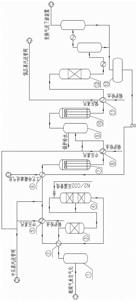
[0031] Such as figure 1 As shown, the CO conversion process of this embodiment is as follows:

[0032] (1) The crude gas sent from aerospace pulverized coal gasification has a temperature of 213°C, a pressure of 3.72MPaG, and a CO dry basis molar content of about 68%. Due to heat loss during the process of transporting the crude gas from the gasification device to the conversion device through pipelines, A small amount of water vapor in the crude gas will condense to form condensate, which will corrode pipes and equipment. Therefore, after the crude gas enters the conversion device, it first enters the gas-liquid separator (1) to separate the condensate from the bottom. The crude gas from the top of the gas-liquid separator ⑴ enters the feed heat exchanger ⑵ of the shift furnace, where the crude gas is heated to 260°C by the shift gas, reaching the activation temperature of the catalyst and at the same time higher than the saturation of water vapor in the crude gas temperatur...

Embodiment 2

[0038] Such as figure 1 As shown, the CO conversion process of this embodiment is as follows:

[0039] (1) The crude gas sent from aerospace pulverized coal gasification has a temperature of 201°C, a pressure of 3.72MPaG, and a CO dry basis molar content of about 61%. Due to heat loss during the process of transporting the crude gas from the gasification device to the conversion device through pipelines, A small amount of water vapor in the crude gas will condense to form condensate, which will corrode pipes and equipment. Therefore, after the crude gas enters the conversion device, it first enters the gas-liquid separator (1) to separate the condensate from the bottom. The crude gas from the top of the gas-liquid separator ⑴ enters the feed heat exchanger ⑵ of the shift furnace, where the crude gas is heated to 260°C by the shift gas, reaching the activation temperature of the catalyst and at the same time higher than the saturation of water vapor in the crude gas temperatur...

Embodiment 3

[0045] Such as figure 1 As shown, the CO conversion process of this embodiment is as follows:

[0046] (1) The crude gas sent from aerospace pulverized coal gasification has a temperature of 210°C, a pressure of 3.72MPaG, and a CO dry basis molar content of about 71%. Due to heat loss during the process of transporting the crude gas from the gasification device to the conversion device through pipelines, A small amount of water vapor in the crude gas will condense to form condensate, which will corrode pipes and equipment. Therefore, after the crude gas enters the conversion device, it first enters the gas-liquid separator (1) to separate the condensate from the bottom. The crude gas from the top of the gas-liquid separator ⑴ enters the feed heat exchanger ⑵ of the shift furnace, where the crude gas is heated to 260°C by the shift gas, reaching the activation temperature of the catalyst and at the same time higher than the saturation of water vapor in the crude gas temperatur...


PUM


Abstract

A technology for transforming high Co raw gas obtained through pulverized coal pressure gasification is a technology for transforming raw gas with too high content of carbon monoxide, and can be used in an ammonia synthesis process or a hydrogen production process. The technology comprises the following steps: carrying out a four-stage transforming reaction on the raw gas, carrying out heat recovery, sending the obtained material to a downstream device, and further processing. The raw gas is transformed through a four-stage transforming furnace, heat generated in the reaction is used to heat water supplied to a middling pressure boiler, and a byproduct middle pressure saturated steam generated in the heating process is added to a position in front of the transformation furnace to adjust a water-steam ratio in order to reduce externally supplied steam and reduce energy consumption and systemic resistance drop.

Description

technical field [0001] The invention relates to a crude gas conversion process, in particular to a crude gas conversion process obtained by pressurized gasification of pulverized coal with high CO content. Background technique [0002] Affected by the increasing shortage of petroleum resources, my country's coal chemical industry has entered a stage of rapid development, and projects such as the production of synthetic ammonia and methanol using coal as raw materials have been launched one after another. This has also led to the introduction and application of various coal gasification processes, such as Shell pulverized coal gasification, Aerospace pulverized coal gasification, Lurgi coal gasification and Texaco coal water slurry gasification. Among them, my country's self-developed aerospace pulverized coal gasification process is widely favored by my country's chemical companies because of its wide application to coal types, high content of effective components in syngas,...

Claims


Application Information

Patent Timeline
Patent Type & Authority Patents(China)
IPC IPC(8): C01B3/16
CPCY02P20/10
Inventor 尹俊杰马如芬曹志斌汪旭红杜国强
Owner CHANGZHENG ENG
Learn More