
Discharging pot for powder and particle materials

A material and powder technology, which is applied in the field of powder material unloading tanks, can solve the problems of difficulty in production, increase the speed of the engine to the air compressor, and increase exhaust gas emissions, so as to improve the safety and stability of transportation, unloading, etc. The effect of shortening the material running time and reducing the damage of the machine

Inactive Publication Date: 2015-02-11
衢州市华夏专用汽车有限公司
View PDF7 Cites 4 Cited by
  • Summary
  • Abstract
  • Description
  • Claims
  • Application Information

AI Technical Summary

Problems solved by technology

[0004] (1) The production workload is heavy. Due to the complex structure of the tank truck, it takes a lot of time to manufacture and install, and the installation process is complicated. A defect in one of the steps will cause quality problems, increasing the difficulty of after-sales service and cost;
[0005] (2) Due to the complexity of the internal structure of the tank and the inability to solve the problem of welding gravity of the steel plate and welding in place, many steel plates will crack from time to time, which will make product maintenance troublesome and also cause inconvenience to unloading. One of the small Small slippery boards or fluidized bed boards are cracked, and sometimes it is necessary to manually unload the entire truckload of cement from the feed port;
[0006] (3) The production of sliding plates, fluidized beds, high-pressure gas chambers, and balance pipes requires at least 2 tons of steel, and manual welding between components is required, which greatly increases the cost;
[0007] (4) The production is difficult, the design requirements are high, and the angle between the sliding material plate and the fluidized bed is high. For example, an angle is required for cement loading, an angle is required for lime material, and an angle is required for mineral powder, etc. Unloading will be incomplete and a large amount of residual material will be generated; and because the tank body is different in size and different user requirements are not the same, the technicians must check the angle and thickness of each sliding plate, fluidized bed, and air chamber plate. The size is adjusted, which greatly increases the workload;
[0008] (5) The sliding plate, fluidized bed plate, high-pressure air chamber, balance air pipe, etc. occupy a certain space, which reduces the use space of the transportation medium to a certain extent, and the increase of compressed air due to the increase of space increases the Increase the speed time of the engine to the air compressor, increase the cost, and increase the exhaust emission

Method used

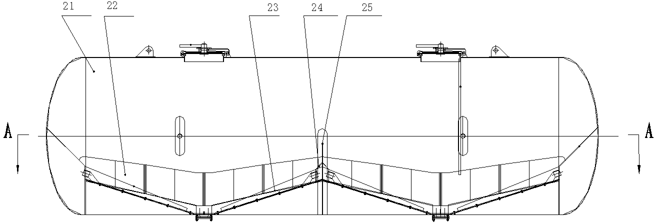
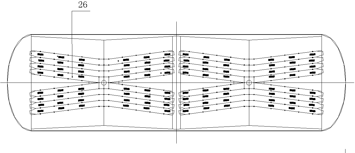
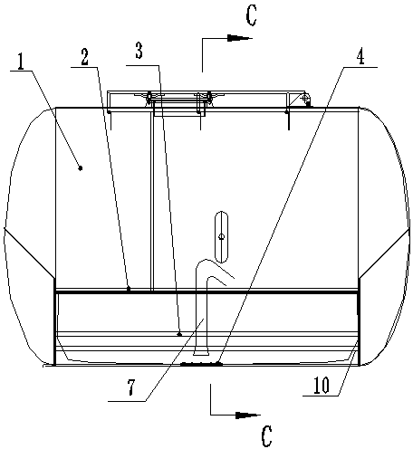

Image

  • Discharging pot for powder and particle materials
  • Discharging pot for powder and particle materials
  • Discharging pot for powder and particle materials

Examples


Embodiment 1

[0037] refer to image 3 , 6 , 7, a discharge tank for powder materials, comprising a tank body 1 and a discharge pipe 7, the bottom of the inner wall of the tank is longitudinally provided with several vent pipes 3, and several vent holes are arranged on the vent pipe 3 , the tank body is provided with an air inlet connected to the ventilation pipe; a fluidized cloth 10 is also fixed around the lower part of the inner wall of the tank, and the surroundings of the fluidized cloth 10 are sealed with the inner wall of the tank body 1, and the central part of the fluidized cloth 10 It is fixed with the center of the bottom of the tank through the flange 4, and the central part of the fluidized cloth 10 has a ventilating area, and the vent pipe 3 is located between the inner wall of the tank and the fluidized cloth 10; the feeding port of the discharge pipe is located in the ventilated 1 to 50 cm above the area.

[0038] The inner wall of the tank is provided with slots 2 around...

Embodiment 2

[0044] refer to Figure 4-9 , a discharge tank for powder materials, comprising a tank body 1 and a discharge pipe 7, the bottom of the inner wall of the tank is longitudinally provided with several vent pipes 3, and several vent holes are opened on the vent pipe 3, the tank The body is provided with an air inlet communicated with the ventilation pipe.

[0045] The lower part of the tank body is divided into three compartments by two compartment plates 6, and fluidized cloth 10 is fixed around the lower part of the inner wall of each compartment. The center of the 10 and the center of the bottom of the sub-bin are fixed by the flange 4, and the central part of the fluidized cloth 10 has a ventilating area 5, and the ventilating pipe 3 is located between the inner wall of the tank and the fluidized cloth 10; the inlet of the discharge pipe 7 The feed port is located 1-50cm above the air-permeable area.

[0046] The inner wall of the tank is provided with slots 2 around, the f...

Embodiment 3

[0053] refer to Figure 10 , different from Example 2, the present embodiment is provided with an air bag 9 at both ends of the sub-bin on the right, the air bag 9 is located between the inner wall of the sub-bin and the fluidized cloth 10, the air bag 9 has a certain degree of air permeability, Air bag 9 sets up independent air intake pipeline and valve. The size of the gas bag can be cylindrical with a diameter of 400-700mm and a length of 1000-1500mm. When cleaning the remaining material, turn on the air inlet switch of the air bag, and the air bag will start to inflate, and the bulging angle of the fluidized cloth at both ends of the sub-bin will increase, which will increase the fluidization degree of the material, and achieve a better effect of unloading and clearing the warehouse. .


PUM

PropertyMeasurementUnit
Thicknessaaaaaaaaaa
Mass per unit areaaaaaaaaaaa

Abstract

The invention relates to a discharging pot for powder and particle materials. The discharging pot comprises a pot body and a discharging tube, wherein a plurality of vent tubes are longitudinally arranged at the bottom of the inner wall of the pot body, a plurality of air outlets are formed in the vent tubes, and air inlets communicated with the vent tubes are formed in the pot body; fluidization cloth is also fixed at the periphery of the lower part of the inner wall of the pot body, the periphery of the fluidization cloth and the periphery of the inner wall of the pot body are sealed, the center of the fluidization cloth is fixed to the center of the bottom of the pot body, a vent region is formed in the central part of the fluidization cloth, and the vent tubes are positioned between the inner wall of the pot body and the fluidization cloth; a feed opening of the discharging tube is positioned 1-50cm above the vent region. According to the discharging pot disclosed by the invention, the original structures of a material sliding board and the like which are in the traditional discharging pot body are eliminated and are changed into a fluidization structure formed by cloth and multiple vent tubes. The discharging pot has the advantages that the cost is low, the structure is simple, the manufacturing and the mounting are easy, the maintenance is convenient, the discharging is convenient and rapid, and the used space is large.

Description

technical field [0001] The invention relates to a discharge tank for powder materials. Background technique [0002] In recent years, due to the country's increased efforts in economic construction and the rapid development of infrastructure, roads, bridges and housing construction, cement, mineral powder, lime powder, mortar, metal powder, rice, corn and other civil and industrial powders The production and sales of granular material media are growing rapidly. Tank trucks, fixed tanks, storage containers, etc. have become the mainstream means of transportation for powder materials due to their advantages of environmental protection, economy, and high efficiency. Tank trucks are suitable for bulk transportation of fly ash, cement, lime powder, ore powder, granular alkali and other powdery dry materials, which can save a lot of packaging resources and loading and unloading labor for the country. [0003] The structure of the existing powder material unloading tank is relati...

Claims


Application Information

Patent Timeline
IPC IPC(8): B65D90/04B65D90/00B65D90/02
CPCB65D90/04B65D90/00B65D90/02
Inventor 邬望云
Owner 衢州市华夏专用汽车有限公司
Learn More