Safety ejection mechanism for injection mould

An ejection mechanism and injection mold technology, applied in the field of injection molds, can solve the problems of crashing side cores, easily crashing and breaking thimbles, increasing the incidence of injection mold safety accidents, and achieving the effect of improving safety performance and stability.

Inactive Publication Date: 2015-02-11
PERLMAN ELECTRICAL KUSN
View PDF7 Cites 2 Cited by
  • Summary
  • Abstract
  • Description
  • Claims
  • Application Information

AI Technical Summary

Problems solved by technology

[0004] However, the side core-pulling mechanism and the ejection mechanism of the prior art often interfere with each other. For example, when the side core-pulling has not been completely drawn out from the injection molded product, the ejection mechanism starts to eject the injection molded product, and in this process, it is extremely difficult. It is easy to break the thimble and damage the side core, thus increasing the incidence of safety accidents in the injection mold production process

Method used


Image

  • Safety ejection mechanism for injection mould
  • Safety ejection mechanism for injection mould

Examples


Embodiment Construction

[0022] In order to make the technical means, creative features, goals and effects achieved by the present invention easy to understand, the present invention will be further described below in conjunction with specific illustrations.

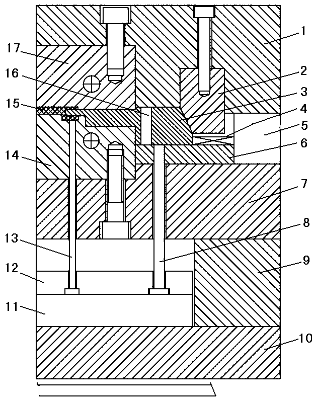
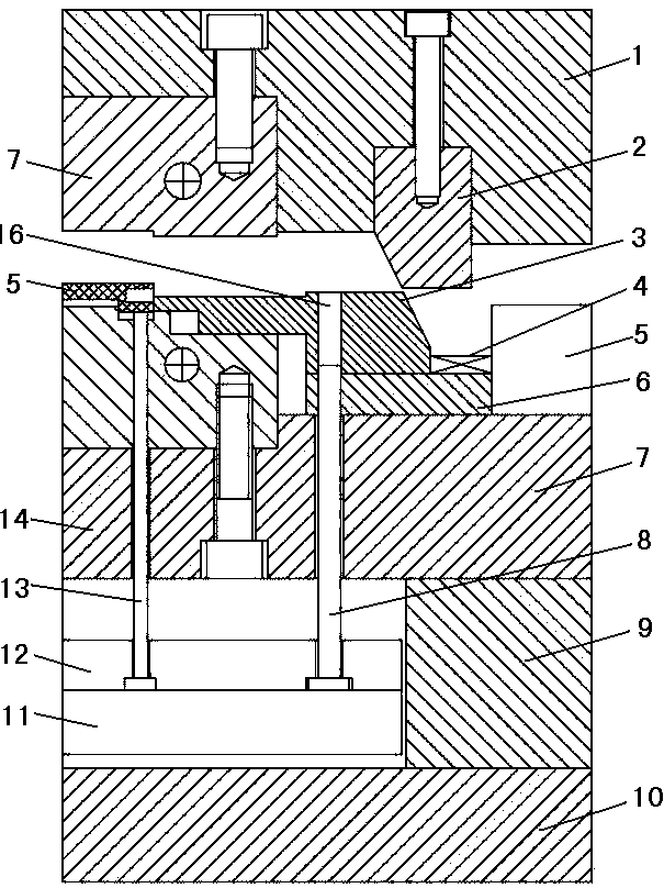
[0023] refer to figure 1 with figure 2 As shown, the present invention is a safety ejection mechanism for an injection mold, including a ejector plate 11, an ejector pin fixing plate 12, an ejector pin 13, a safety ejector pin 8 and a side core-pulling mechanism arranged at the upper end of the safety ejector pin 8;

[0024] In this embodiment, the upper surface of the thimble plate 11 is provided with a thimble fixing plate 12, and the thimble fixing plate 12 fixes the thimble 13 and the safety thimble 8 on the upper surface of the thimble plate 11, and the thimble plate 11 is arranged on the existing lower template 10. There are pads 9 on both sides of the plate, and a male template 7 is provided on the upper surface of the pad 9, and a male...


PUM


Abstract

The invention discloses a safety ejection mechanism for an injection mould; the safety ejection mechanism for the injection mould comprises an ejector pin plate, an ejector pin fixing plate, an ejector pin, a safety ejector pin and a lateral core pulling mechanism arranged at the upper end of the safety ejector pin; the ejector pin fixing plate is arranged on the upper surface of the ejector pin plate; the ejector pin and the safety ejector pin are fixed on the upper surface of the ejector pin plate by the ejector pin fixing plate; the lateral core pulling mechanism comprises a lateral pulled core, a reset spring and a pressure block, wherein the reset spring is arranged at one end of the lateral pulled core; the pressure block is arranged at the upper side of the lateral pulled core and mutually matched with the lateral pulled core; and a safety hole matched with the safety ejector pin is formed in the lateral pulled core. The safety ejection mechanism for the injection mould, disclosed by the invention, has the specific advantages of being reasonable in design, simple in structure, high in safety performance, low in cost and long in service life; in addition, after injection molding, the ejector pin and the lateral pulled core cannot be interfered with each other when an injection product is ejected by the ejector pin.

Description

technical field [0001] The invention relates to the technical field of injection molds, in particular to a safety ejection mechanism for injection molds. [0002] Background technique [0003] At present, during the injection molding process of injection molded products, after the injection molding of the injection molded product is completed, an ejector pin is required to push the injection molded product out of the male mold, and because some injection molded products have undercuts, side pumping is required during the injection molding process core mechanism to complete. [0004] However, in the prior art, the side core-pulling mechanism and the ejection mechanism often interfere with each other. For example, when the side core-pulling has not been completely drawn out of the injection molded product, the ejection mechanism starts to eject the injection molded product, and in this process, it is extremely difficult. It is easy to break the thimble and damage the side co...

Claims


Application Information

Patent Timeline
IPC IPC(8): B29C45/40B29C45/33B29C45/84
CPCB29C45/4005B29C45/33B29C45/84
Inventor 周军
Owner PERLMAN ELECTRICAL KUSN
Why Eureka
Try Eureka