
Trajectory control device for articulated robot, and control method

A multi-joint robot and trajectory control technology, applied in the direction of robot, computer control, program control, etc., can solve the problems of low vibration frequency, trajectory error, and no speed feedforward

Active Publication Date: 2015-02-04
KOBE STEEL LTD
View PDF10 Cites 7 Cited by
  • Summary
  • Abstract
  • Description
  • Claims
  • Application Information

AI Technical Summary

Problems solved by technology

However, since the natural frequency is low, from the viewpoint of vibration suppression, speed feedforward, etc. are hardly used
Therefore, the phase lag of the actual feedback value is large relative to the target value, and the response characteristics of the speed control unit of the servo control unit are different for each axis, resulting in a trajectory error.
In addition, since the position / speed control characteristics of the servo control unit change due to inertial changes (especially phase lag characteristics) accompanying changes in the posture of the robot, even if the inverse calculation of the inter-axis interference torque etc. is performed based on the target value And compensated nonlinear compensation control, also can hardly function effectively due to phase deviation

Method used


Image

  • Trajectory control device for articulated robot, and control method
  • Trajectory control device for articulated robot, and control method
  • Trajectory control device for articulated robot, and control method

Examples


no. 1 Embodiment approach

[0047] [overall composition]

[0048] First, an outline of a vertical articulated robot (hereinafter sometimes simply referred to as an articulated robot) using the trajectory control device according to the present embodiment will be described.

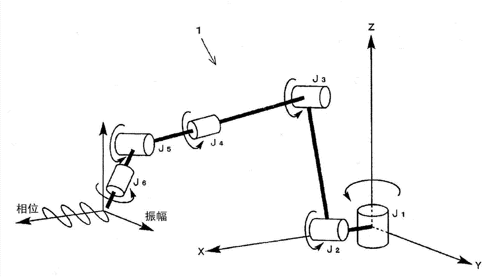
[0049] figure 1 It is an example of a robot that performs a tilting motion (swing motion) of a welding torch, and is a diagram showing an outline of an articulated robot 1 employing a trajectory control device according to this embodiment. The articulated robot 1 is of a vertical articulated type and includes six joints J1 to J6, and performs arc welding with a welding wire fed from a welding torch provided at the tip of the axis of J6. The articulated robot 1 sets a welding operation interval between a predetermined welding start point and a welding end point, moves in the direction of a welding line connecting the welding start point and welding end point, and sets the welding wire so that A tilting motion (swinging motion) is pe...

no. 2 Embodiment approach

[0083] Hereinafter, a trajectory control device according to a second embodiment of the present invention will be described. In addition, the trajectory control device according to the present embodiment is different from the trajectory control device 10 according to the above-mentioned first embodiment in the provision method of the first dynamic characteristic calculation unit 300 . Other than that, it is the same as that of the first embodiment, so the parts that overlap with the above description will not be repeated.

[0084] In the first embodiment described above, the second dynamic characteristic calculation unit 400 is provided with a high-frequency rejection characteristic equal to or greater than that of the first dynamic characteristic calculation unit 300 . In the present embodiment, the second dynamic characteristic calculation unit 400 is provided with a very strong high-frequency blocking characteristic similarly to the first embodiment. In addition, the first...

no. 3 Embodiment approach

[0106] Hereinafter, a trajectory control device according to a third embodiment of the present invention will be described. In addition, the trajectory control device according to the present embodiment is different from the trajectory control device 10 according to the above-mentioned first embodiment in the provision method of the first dynamic characteristic calculation unit 300 . Other than that, it is the same as that of the first embodiment, so the parts that overlap with the above description will not be repeated.

[0107] Since the current control characteristic responds very quickly, considering that good performance can be obtained even if it is close to "gain = 1", Formula (1) can be transformed into the following Formula (5).

[0108] [Formula 5]

[0109] Gp · Gv · s + Gp · Gi J ...


PUM


Abstract

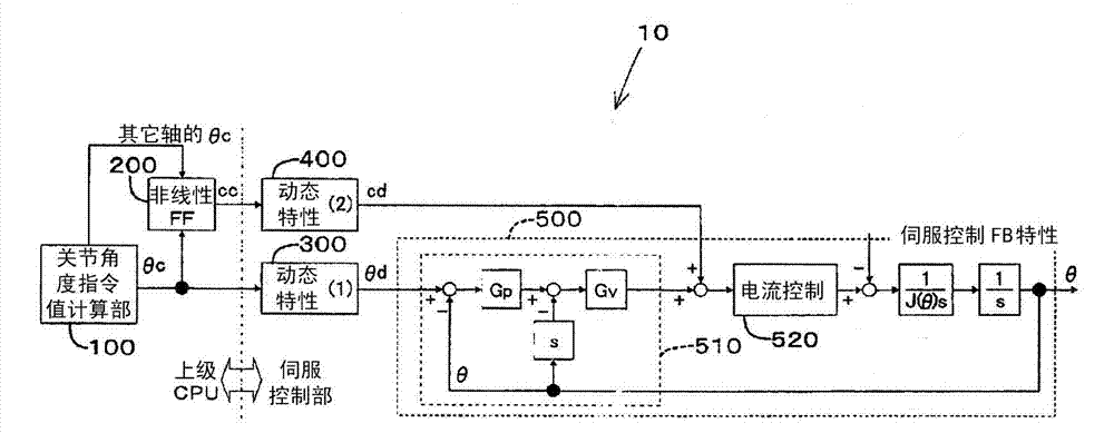
In a trajectory control device (10) for an articulated robot, a first dynamic characteristic calculation unit (300) is provided with a high-frequency cutoff characteristic having a cutoff frequency which is lower than the natural oscillation frequency of the robot, performs filtering processing with respect to a joint-angle command value (thetac), and outputs a processed joint-angle target value (thetad). A second dynamic characteristic calculation unit (400) is provided with a high-frequency cutoff characteristic having a cutoff frequency which is lower than that of the first dynamic characteristic calculation unit (300), performs filtering processing with respect to the output from an interference-torque compensation command value calculation unit (200), and outputs a processed interference-torque compensation value (cd).

Description

technical field [0001] The present invention relates to control of an articulated robot used in, for example, arc welding, and in particular to trajectory control of an articulated robot capable of weaving with high trajectory accuracy. Background technique [0002] When welding a plurality of base metals by arc welding, weaving welding is used in which welding is carried out by moving a welding electrode in a sinusoidal swinging motion in the left and right directions of a welding line while advancing in a welding direction. This swing welding has conventionally been performed by swinging the welding torch itself from side to side, or by tilting the welding torch around the welding torch itself. When an articulated robot is used to perform such weaving welding, high trajectory accuracy is required. [0003] In such an articulated robot, servo control is performed on an axis-by-axis basis. However, since the natural frequency is low, from the viewpoint of vibration suppres...

Claims


Application Information

Patent Timeline
Patent Type & Authority Applications(China)
IPC IPC(8): B25J9/10B23K9/095B23K9/12G05B19/4093
CPCB23K9/0216G05B2219/41166B25J9/1633G05B2219/45104G05B19/4093B23K9/12G05B2219/49384B23K9/095B23K9/173B25J9/1664G05B2219/41124G05B2219/41426G05B2219/42065Y10S901/02B25J9/10B25J9/06B25J9/163
Inventor 西田吉晴和田尧井上芳英稻田修一
Owner KOBE STEEL LTD
Learn More