
High energy strong current accelerator Faraday cup

A technology of Faraday cages and Faraday cages, which is applied in the direction of instruments, scientific instruments, measuring devices, etc., and can solve problems such as easy damage, inconvenient installation, and Faraday cages that cannot be replaced and maintained, so as to increase the water cooling effect and shorten the axial direction. The effect of length and increasing the contact area

Active Publication Date: 2017-06-16
INST OF MODERN PHYSICS CHINESE ACADEMY OF SCI
View PDF4 Cites 0 Cited by
  • Summary
  • Abstract
  • Description
  • Claims
  • Application Information

AI Technical Summary

Problems solved by technology

[0008] 1) Solve the problem that the traditional Faraday cage is easily damaged in the case of high energy and strong flow because of its structural shape and non-surface contact between the intercepting surface and the water cooling body;
[0009] 2) Solve the problem that the traditional Faraday cage cannot be replaced and repaired after the Faraday cage is damaged because the head of the Faraday cage and the driving device are designed as a whole;
[0010] 3) Solve the problem that the traditional Faraday cage is inconvenient to install because the head of the Faraday cage and the driving device are designed as a whole, and the angle of the head of the Faraday cage is fixed.

Method used


Image

  • High energy strong current accelerator Faraday cup
  • High energy strong current accelerator Faraday cup
  • High energy strong current accelerator Faraday cup

Examples


Embodiment 1

[0037] Example 1: see figure 1 , a high-energy strong current accelerator Faraday cage, its main feature is that the Faraday cage head 8 is connected to the drive device 1 through the adapter flange 7 and the looper flange 6, and the Faraday cage head 8 and the drive device 1 are independent of each other.

[0038] The water inlet pipe 5, the water outlet pipe 4, the high-voltage cable 2, and the signal cable 3 of the Faraday cage head 8 pass through the adapter flange 7 and the looper flange 6 and extend through the support cylinder 44 of the drive device 1 to Atmospheric end: the adapter flange 7 and the looper flange 6 are provided with knife edges, and copper pads are added between the two flanges, and the bolts are connected to seal, realizing the isolation of the atmosphere and the vacuum. .

Embodiment 2

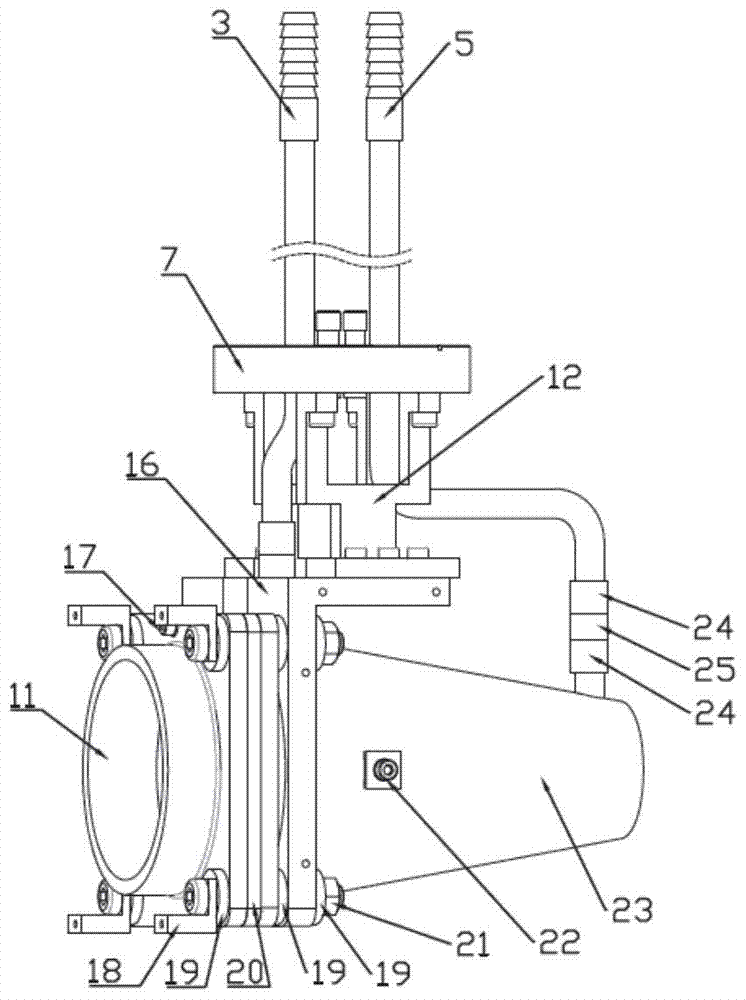
[0039] Example 2: see figure 1 , figure 2 , image 3 , Figure 4 , the Faraday cage of the high-energy strong current accelerator, the Faraday cage 23 is conical, the innermost layer is a frustum-shaped intercepting surface 26, and the small end of the frustum-shaped intercepting surface 26 is connected with a cone top 30, the cone top The inner cavity surface of 30 and the frustum-shaped intercepting surface 26 are conical surfaces with the same taper, and the cone-top sealing sheet 31 is arranged on the top of the cone-top 30 to seal the cone-top inside the water-cooling body 48; the water-cooling body 48 is arranged on the frustum-shaped intercepting surface 26 and the outside of the conical top 30, the truncated conical intercepting surface 26, the conical top 30 and the water cooling body 48 are in surface contact. The water-cooling body 48 is provided with a spiral water channel 29 , which forms a cooling water channel together with the water channel back plate 28 . ...

Embodiment 3

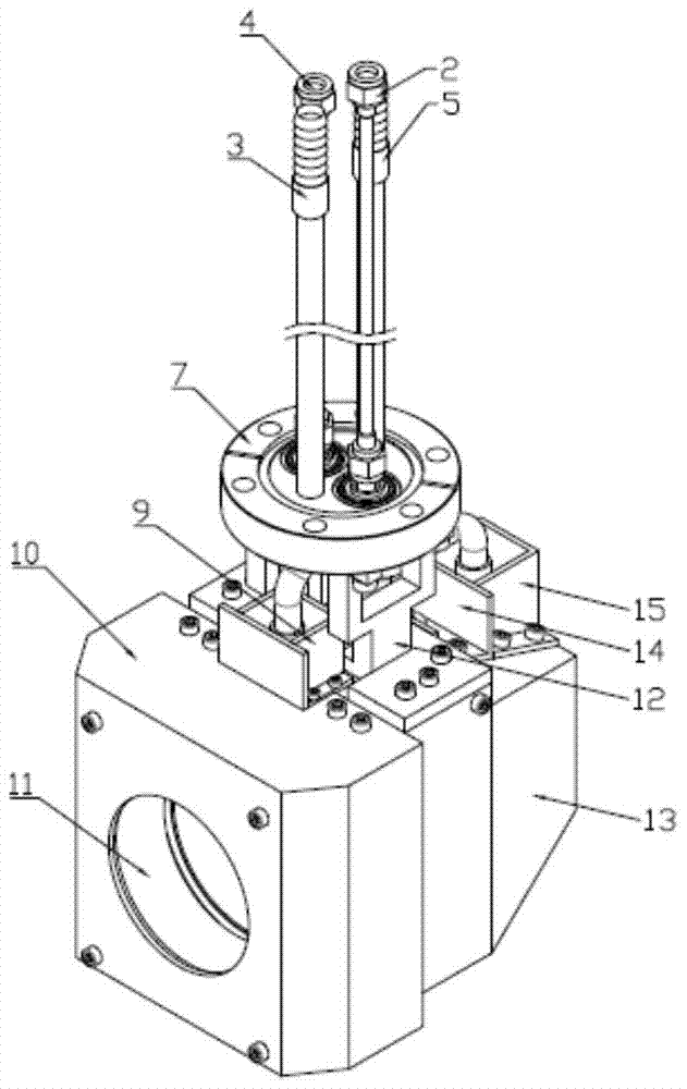
[0045] Embodiment 3: see Figure 1 to Figure 9 , a Faraday cage for a high-energy strong current accelerator, consisting of a Faraday cage head 8 and a driving device 1 that are independent of each other, and they are connected by an adapter flange 7 and a looper flange 6 .

[0046] The water inlet pipe 5, the water outlet pipe 4, the high-voltage cable 2, and the signal cable 3 of the Faraday cage head 8 pass through the support cylinder 44 of the drive device 1 and are connected by the adapter flange 7 and the loop flange 6, The transfer flange 7 and the looper flange 6 have their own knife edges, and copper pads are added between them, and they are sealed by bolts.

[0047] The Faraday cage head 8 is composed of a water inlet pipe 5, an outlet pipe 4, a high voltage cable 2, a signal cable 3, an adapter flange 7, a flange bracket 12, a Faraday cage bracket 16, an electrode 11, a Faraday cage 23 and Baffle plate (front baffle plate 10, rear baffle plate 13, water inlet pipe...


PUM


Abstract

The invention provides a Faraday cylinder for a high-energy high-current accelerator. The Faraday cylinder is mainly characterized in that the head portion of the Faraday cylinder is connected with a driving device through an adapter flange and a loose flange, and the head portion of the Faraday cylinder and the driving device are mutually independent. According to the Faraday cylinder for the high-energy heavy-current accelerator, a water inlet pipe, a water outlet pipe, a high-voltage cable and a signal cable on the head portion of the Faraday cylinder pass through the adapter flange and the loose flange and pass through the support cylinder of the driving device to extend to an atmosphere end. The adapter flange and the loose flange are each provided with a cutting edge, a copper pad is additionally arranged between the two flanges, and the two flanges are connected and sealed through a bolt, such that an atmosphere is isolated from a vacuum. According to the invention, the direction of the head portion of the Faraday cylinder can be conveniently adjusted, the head portion of the Faraday cylinder can be conventionally replaced, and convenience is brought to installation and maintenance. The interception surface of the Faraday cylinder and a water cooling body are in surface contact with each other, such that the water cooling effect is effectively enhanced. The conic node of the interception surface is easy to process, and the processed conic node is a point; and the field angle at the bottom of a cone effectively reduces the axial length of the cone.

Description

technical field [0001] The invention relates to a beam current diagnostic equipment used in an accelerator device, in particular to a Faraday cage used in a high-energy intensive current accelerator device. Background technique [0002] The Faraday cup is an intercepting beam diagnostic device commonly used in accelerator devices. Its function is not only to block and intercept the beam, but also to measure the intensity of the beam. Because it was first designed and used by Faraday, it is often called a Faraday cage. Its structure is generally a cylindrical collecting electrode. When the beam (a collection of charged particles) bombards the electrode and is intercepted and collected by the electrode, the charge carried by the beam flows through the resistor to form a loop, thereby measuring the current intensity of the beam. . [0003] The Faraday cage is an intercepting beam diagnostic device. When the beam is intercepted, its energy will be deposited on the intercepting...

Claims


Application Information

Patent Timeline
Patent Type & Authority Patents(China)
IPC IPC(8): G01T1/29
Inventor 张惊蛰武军霞毛瑞士康新才张雍朱光宇李敏苏弘赵铁成夏佳文原有进骆宏尹炎王延谋王慜马维年徐智国
Owner INST OF MODERN PHYSICS CHINESE ACADEMY OF SCI
Learn More