
High temperature prevention infrared temperature measurement equipment

An infrared temperature measurement and anti-high temperature technology, which is applied in the field of infrared thermometers, can solve the problems of short detection range, unsteady hands when the hands are heated, and achieve the effect of preventing human hands from being heated

Inactive Publication Date: 2015-02-04
JING LIN CHENGDU SCI & TECH
View PDF5 Cites 0 Cited by
  • Summary
  • Abstract
  • Description
  • Claims
  • Application Information

AI Technical Summary

Problems solved by technology

[0003] The purpose of the present invention is to overcome the deficiencies of the current technology and provide a high-temperature infrared temperature-measuring device to solve the problem that the detection range of the existing infrared temperature-measuring device is too close. Feel the high temperature, the hand is heated to the defect of holding the device stably

Method used


Image

  • High temperature prevention infrared temperature measurement equipment
  • High temperature prevention infrared temperature measurement equipment
  • High temperature prevention infrared temperature measurement equipment

Examples


Embodiment 1

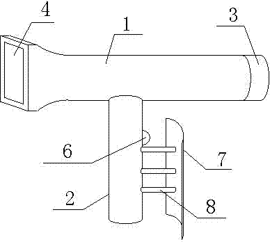
[0017] Such as figure 2 As shown, the anti-high temperature infrared temperature measuring equipment includes a body 1 and a handle 2 vertically installed under the body 1. The handle 2 is provided with a hand guard 7, and the hand guard 7 is arranged on the handle 2 close to the infrared On the end face of the sensor 3, the hand guard 7 is connected to the handle 2 through three connecting rods 8, and the connecting rods 8 are arranged at intervals along the extending direction of the handle 2, and the distance between adjacent connecting rods 8 is 2-3 cm. In this device, a hand guard 7 is set on the side of the handle 2 facing the infrared sensor, and the infrared sensor 3 is to face the fire source, so the hand guard 7 is arranged on the side of the handle 2 facing the fire source, and the hand guard 7 passes through Three connecting rods 8 are connected to the handle 2. When using the thermometer, the staff holds the handle 2 with their hands, and the three connecting rod...

Embodiment 2

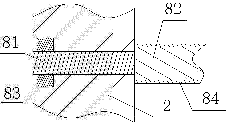
[0019] Such as image 3 , the structure of this embodiment is basically the same as that of Embodiment 1, the difference is that the connecting rod 8 and the handle 2 are flexibly connected, the connecting rod 8 includes a mounting part 81 and a connecting part 82, and the diameter of the connecting part 82 is larger than that of the mounting part 81, the installation part 81 runs through the handle 2, and is exposed at the other end of the handle 2, and the exposed part of the installation part 81 is provided with an external thread, and the handle 2 is clamped by the nut 83 and the connecting part 82, so that the connecting rod 8 and the handle 2 Fixation in the direction of extension. This installation method can make the hand guard block 7 detachable. After using the thermometer, the nut 83 is unscrewed, the connecting rod 8 is extracted from the handle 2, and the hand guard block 7 is removed, which avoids the During the transportation process, due to collision with the ...


PUM


Abstract

The invention discloses high temperature prevention infrared temperature measurement equipment. The equipment comprises a machine body (1) and a handle (2) vertically installed below the machine body (1), wherein the handle (2) is provided with a hand protecting separation blade (7) is arranged on one end plane of the handle (2) nearby a near-infrared sensor (3) and connected with the handle (2) through three connecting rods (8), the connecting rods (8) are alternatively arranged in an extending direction of the handle (2) and the space between two adjacent connecting rods (8) is 2-3cm. The high temperature prevention infrared temperature measurement equipment provided by the invention has the beneficial effects that the hand protecting separation blade is arranged on the handle and is used for separating the handle of a worker from a combustion source and is used for separating the temperature and preventing the problems of damaging a thermodetector because the device cannot be taken unstably because the hands are heated when the equipment is in use; furthermore, the hand protecting separation blade is movably connected with the handle when the hand protecting separation blade is not in use, i.e. taking down the hand protecting separation blade and preventing the separation blade being damaged due to conveying.

Description

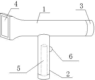
technical field [0001] The invention relates to an infrared thermometer, in particular to a high temperature resistant infrared temperature measuring device. Background technique [0002] Infrared temperature measuring equipment generally includes a body (1) and a handle (2) arranged under the body (1), such as figure 1 , one end of the body (1) is provided with an infrared sensor (3), and the other end is provided with a display screen (4), the signal of the infrared sensor (3) is connected to the display screen (4) through a processor, and the handle (2) is provided with a power supply ( 5), the power supply (5) supplies power to the infrared sensor (3) and the display screen (4), and the handle (2) is also provided with a power switch (6). 3-5m, the staff will feel high temperature when the handheld device is 3-5m away from the fire source, especially the hand holding the handle, because it is close to the front end, so the temperature felt is the highest, making the sta...

Claims


Application Information

Patent Timeline
Patent Type & Authority Applications(China)
IPC IPC(8): G01J5/02
Inventor 曾衡东吴海宁殷刚
Owner JING LIN CHENGDU SCI & TECH
Learn More