
Antenna feeder tester and extending device error correction method

A technology for extended devices and testers, which is applied in the field of extended device error correction, and can solve problems such as low efficiency, mismatched test ports, and inability to calibrate

Active Publication Date: 2015-01-28
CHINA ELECTRONIS TECH INSTR CO LTD
View PDF8 Cites 29 Cited by
  • Summary
  • Abstract
  • Description
  • Claims
  • Application Information

AI Technical Summary

Problems solved by technology

[0008] However, in many actual measurement situations, it is impossible to calibrate on the test end face of the DUT, such as probe measurement, or the use of extension lines such as cables, which cause the test port to not match the calibration part, etc.
In this case, at present, only the test port of the instrument is calibrated, and the extension device and the DUT are measured as a whole, ignoring the influence caused by the extension device, because the test end face of the DUT is inconsistent with the calibration end face, and There is a large error
In addition, if the end face of the extension device can be calibrated, the antenna feeder tester can be recalibrated on the end face of the extension device to improve the measurement accuracy, but the efficiency is low

Method used


Image

  • Antenna feeder tester and extending device error correction method
  • Antenna feeder tester and extending device error correction method
  • Antenna feeder tester and extending device error correction method

Examples


Embodiment Construction

[0053] Below in conjunction with accompanying drawing and specific embodiment the present invention is described in further detail:

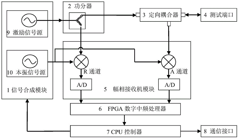
[0054] combine figure 2 As shown, an antenna feeder tester includes a signal synthesis module 1 , a power divider 2 , a directional coupler 3 , a test port 4 , an amplitude-phase receiver module 5 , an FPGA digital intermediate frequency processor 6 and a CPU controller 7 .

[0055] Wherein, the signal synthesis module 1 includes an excitation signal source 9 and a local oscillator signal source 10 .

[0056]The amplitude-phase receiver module 5 includes an R channel and an A channel, and an A / D conversion module is respectively arranged behind the R channel and the A channel.

[0057] The excitation signal source 9 is used to generate an excitation signal and send the generated excitation signal to the power divider 2 .

[0058] The power divider 2 is used to divide the excitation signal into two paths, one path is sent to the R channel as a...


PUM


Abstract

The invention discloses an antenna feeder tester and an extending device error correction method by using the antenna feeder tester. The antenna feeder tester comprises a signal synthesis module, a power divider, a directional coupler, a test port, an amplitude and phase receiver module, an FPGA digital intermediate frequency processor and a CPU controller, wherein the signal synthesis module comprises an excitation signal source and a local vibration signal source; and the amplitude and phase receiver module comprises an R channel and an A channel, and one A / D conversion module is arranged behind each of the R channel and the A channel. During measurement, after correction is finished at the test port of the instrument, the antenna feeder tester of the invention is then used to measure transmission parameters of an extending device in the case when the extending device is connected, the transmission parameters of the extending device are used for correcting test data when the extending device is connected with a tested piece according to a theoretical loss formula of a cable, correction does not need to be carried out again, and the measurement precision and the test efficiency are thus improved.

Description

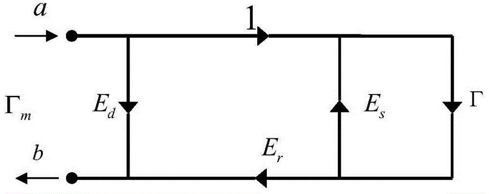
technical field [0001] The invention relates to an antenna feeder tester and an extension device error correction method completed by using the antenna feeder tester when the extension device is connected. Background technique [0002] Due to the imperfection of its hardware system, the antenna feeder tester has systematic errors. At present, the antenna feeder tester must be calibrated before measurement to correct the system error. The systematic error of the antenna feeder tester can be expressed by an error model with three error coefficients, such as figure 1 Shown: The three error coefficient items are E d (directivity), E s (source match) and E r (reflection tracking), a is the incident wave, b is the reflected wave, Γ m is the measured reflection coefficient, and Γ is the actual reflection coefficient. [0003] The relationship between the error coefficient item, the measured value of the reflection coefficient and the actual value of the reflection coefficient...

Claims


Application Information

Patent Timeline
Patent Type & Authority Applications(China)
IPC IPC(8): G01R31/00G01R35/00
Inventor 郑恢康孙林祝林林
Owner CHINA ELECTRONIS TECH INSTR CO LTD
Learn More