
Reaction cup loading mechanism for full-automatic chemiluminiscence immune analyzer

An automatic chemistry and luminescence immune technology, applied in analytical materials, instruments, biological tests, etc., can solve the problems of low degree of automation, inability to load the cuvette, and inability to meet the continuous operation of the instrument, and achieve the effect of a compact overall structure.

Active Publication Date: 2015-01-28
郑州博赛生物技术股份有限公司
View PDF5 Cites 2 Cited by
  • Summary
  • Abstract
  • Description
  • Claims
  • Application Information

AI Technical Summary

Problems solved by technology

At present, the plate rack with the reaction cup is mainly placed on the operating table by manual operation, and the plate rack is removed by manual operation after the cuvette is used. Since this series of work is mainly completed manually, the degree of automation is low, and the reaction cup is placed in the reaction at one time. The cup cannot meet the continuous work of the instrument for a long time
With the development of science and technology, some semi-automatic cuvette loading mechanisms have appeared, but the existing loading mechanism cannot fully automatically and accurately load the cuvettes into the cuvette recognition mechanism, and then successfully load the cuvettes into the luminescence immunoassay analyzer The process of subsequent fully automated analysis in

Method used


Image

  • Reaction cup loading mechanism for full-automatic chemiluminiscence immune analyzer
  • Reaction cup loading mechanism for full-automatic chemiluminiscence immune analyzer
  • Reaction cup loading mechanism for full-automatic chemiluminiscence immune analyzer

Examples


Embodiment Construction

[0019] The present invention will be further described in detail below in conjunction with the accompanying drawings, so that those skilled in the art can implement it with reference to the description.

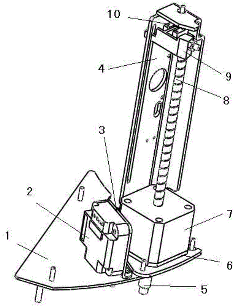
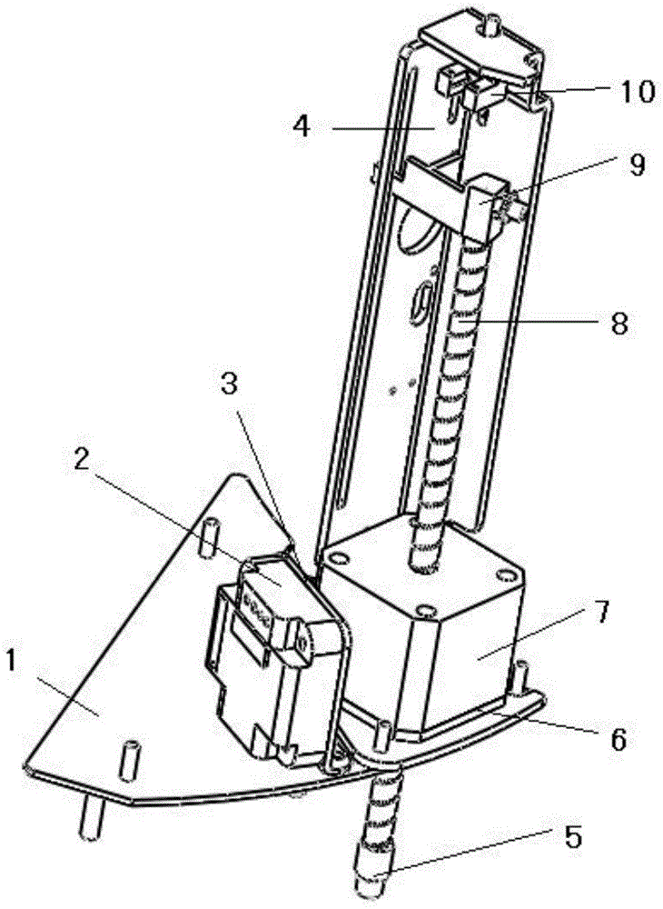
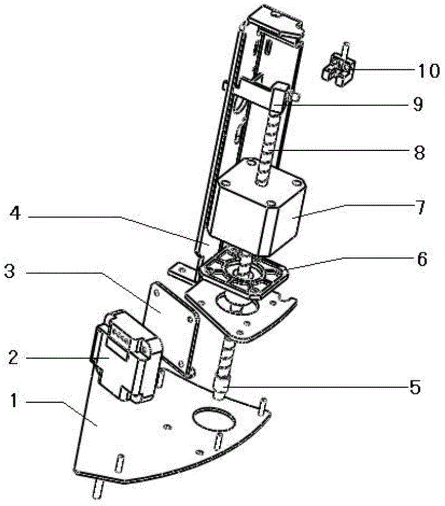
[0020] See attached figure 1 to attach image 3 As shown, it is a cuvette loading mechanism for a fully automatic chemiluminescent immunoassay analyzer according to an embodiment of the present invention, including a fixed plate 1, which is a flat plate structure, and acts as a load-bearing support, vertically on the fixed plate 1 A support 4 and a module mounting plate 3 are provided, and the module mounting plate 3 is used to fix the motor drive module 2; the screw motor 7 is fixed on the support 4, and the screw 8 motor 7 and the support 4 There is also a guide and positioning block 6 fixed between them. The center of the guide and positioning block 6 is a cylindrical through hole protruding downwards. The screw mandrel 8 is a threaded hollow rod-shaped structure, and th...


PUM


Abstract

The invention discloses a reaction cup loading mechanism for a full-automatic chemiluminiscence immune analyzer. The reaction cup loading mechanism comprises a fixing plate, a screw rod motor, a screw rod and a guide induction block, wherein the fixing plate is vertically provided with a bracket and a module mounting plate; the module mounting plate is used for fixing a motor driving module; the screw rod motor is fixed on the bracket; a guide positioning block is also fixedly arranged between the screw rod motor and the bracket; a cylindrical through hole raised downward is formed in the center of the guide positioning block; the cylindrical through hole penetrates from the bracket bottom plate through hole and the fixing plate through hole; the screw rod motor is electrically connected with the motor driving module; the screw rod is in a thread hollow rod-shaped structure; the screw rod successively penetrates through the screw rod motor and the cylindrical through hole along the axial direction of the screw rod; one end of the guide induction block is connected with the top end of the screw rod and the other end is embedded in a chute on the side wall of the bracket, wherein the motor driving module drives the screw rod motor to drive the screw rod and a die head to move; and the screw rod motor finishes once loading movement.

Description

technical field [0001] The invention relates to a fully automatic chemiluminescence immunoassay analyzer, in particular to a cuvette loading mechanism for a fully automatic chemiluminescence immunoassay analyzer. Background technique [0002] Reaction cups are mainly used in the medical device industry, especially in automatic chemiluminescence immunoassay analyzers. At present, the plate rack with the reaction cup is mainly placed on the operating table by manual operation, and the plate rack is removed by manual operation after the cuvette is used. Since this series of work is mainly completed manually, the degree of automation is low, and the reaction cup is placed in the reaction at one time. The cup cannot meet the continuous work of the instrument for a long time. With the development of science and technology, some semi-automatic cuvette loading mechanisms have appeared, but the existing loading mechanism cannot fully automatically and accurately load the cuvettes in...

Claims


Application Information

Patent Timeline
IPC IPC(8): G01N35/04G01N35/00G01N33/53
Inventor 陈月岩钱英帅洪
Owner 郑州博赛生物技术股份有限公司
Learn More