


Quick Research
Generate reliable direction feasibility study reports for your R&D in just a few steps.

Technical Q&A
Discover and master advanced knowledge NOW. Basics, ideas, possibilities, all at once.

Find Solutions
As an expert in R&D theories, this can generate solutions to your technical problems instantly.

Evaluate Feasibility
Analyze your overall solution with one click, know your potential R&D risks in advance.

Monitor Landscape
Get weekly tech updates, stay abreast of the latest tech innovations and key insights.
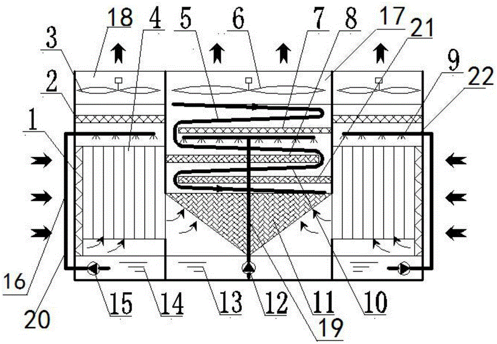
Evaporative condensers for peak cooling in power plants
An evaporative condenser and peak cooling technology, which is applied in steam/steam condensers, lighting and heating equipment, etc., can solve the problem of limited condensation efficiency of evaporative condensers, reduced heat transfer temperature difference of air-cooled condensers, and Surface dirt and other problems, to achieve the effect of increasing the latent heat of vaporization, improving heat transfer efficiency, and increasing the contact area
- Summary
- Abstract
- Description
- Claims
- Application Information
AI Technical Summary
Problems solved by technology
Method used
Image

Examples
Embodiment Construction
[0025] The present invention will be described in detail below in conjunction with the accompanying drawings and specific embodiments.
[0026] The evaporative condenser for power plant peak cooling of the present invention has a structure such as figure 1 As shown, it includes a condenser shell, and an air inlet 16 is arranged on the opposite side walls of the condenser shell, and a packing-coil compound evaporative cooling unit is arranged in the condenser shell, and the packing-coil compound A standpipe type indirect evaporative cooling unit is symmetrically arranged on the left and right sides of the evaporative cooling unit, and an air outlet a17 is arranged on the top wall of the condenser shell corresponding to the filler-coil composite evaporative cooling unit. An air outlet b18 is respectively arranged on the top wall of the corresponding condenser shell above the vertical pipe type indirect evaporative cooling units.
[0027] A fan a6 is arranged in the air outlet a...
PUM
 Abstract
Description
Claims
Application Information
 - R&D Engineer
- R&D Manager
- IP Professional
- Industry Leading Data Capabilities
- Powerful AI technology
- Patent DNA Extraction
Browse by: Latest US Patents, China's latest patents, Technical Efficacy Thesaurus, Application Domain, Technology Topic, Popular Technical Reports.
© 2024 PatSnap. All rights reserved.Legal|Privacy policy|Modern Slavery Act Transparency Statement|Sitemap|About US| Contact US: help@patsnap.com