
Improved grounding device

A grounding device, an improved technology, applied in the direction of connecting components, pins, mechanical equipment, etc., can solve the problems of ineffective leakage protection, endangering the safety of life and property, and failure of grounding function, so as to achieve simple structure and ensure the safety of life and property , the effect of preventing loosening

Inactive Publication Date: 2015-01-28
智方设计股份有限公司
View PDF0 Cites 4 Cited by
  • Summary
  • Abstract
  • Description
  • Claims
  • Application Information

AI Technical Summary

Problems solved by technology

[0002] With the continuous development of the social economy and the continuous improvement of the production level of enterprises, various electrical equipment have appeared on the market, and the electrical equipment in every family is also increasing, especially in factories. All equipment needs to use electricity; in order to improve the safety of electrical equipment and mechanical equipment, most electrical equipment and mechanical equipment need to ground the shell. During the grounding of electrical equipment and mechanical equipment, grounding rods are usually required. Most of the currently used grounding rods are a single metal rod, but the currently used grounding rod is a single metal rod, which is easy to cause loosening of the grounding rod in long-term use, and the currently used grounding rod It cannot achieve good contact with the earth, which can easily lead to the failure of the grounding function. After the grounding function fails, once the electrical equipment and mechanical equipment have leakage, they will not be able to protect the leakage, and even endanger people's lives and property.

Method used


Image

  • Improved grounding device

Examples


Embodiment Construction

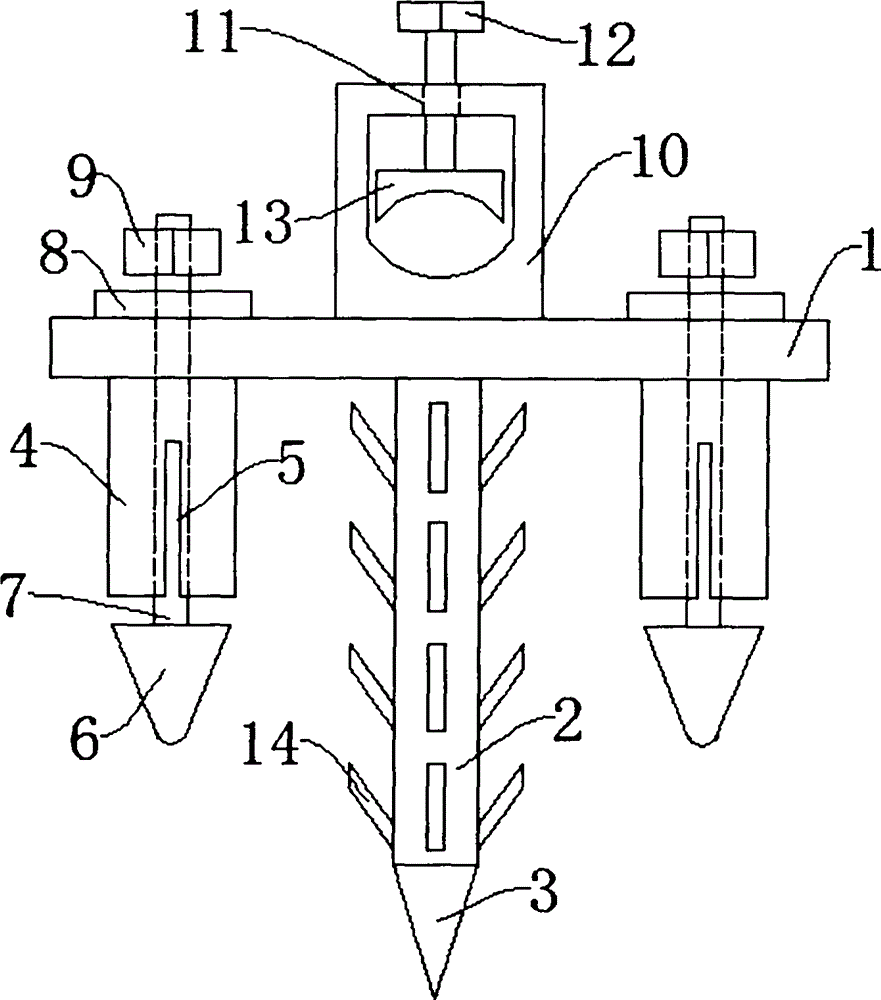
[0012] like figure 1 The improved grounding device shown includes a base plate 1; the bottom of the base plate 1 is fixedly connected with a rod 2; the bottom of the rod 2 is integrally formed with a vertebral body 3; cylinder 4; the sleeve 4 is provided with notches 5 around; the expansion cone 6 is arranged under the sleeve 4; the top of the expansion cone 6 is movably connected with a screw 7; the screw 7 runs through the sleeve 4 in turn Set with the substrate 1; the screw 7 is movably sleeved with a gasket 8; the top of the screw 7 is threadedly connected with a nut 9; the top of the substrate 1 is fixedly provided with a terminal block 10; the top of the terminal block 10 runs through A through hole 11 is provided; a bolt 12 is inserted into the through hole 11 , and the bolt 12 is connected to the through hole 11 through threads; a pressure plate 13 is movably connected to the lower end of the bolt 12 .

[0013] Wherein, the outer side of the rod body 2 is integrally f...


PUM


Abstract

The invention discloses an improved grounding device. The improved grounding device comprises a substrate, wherein a rod body is fixedly connected to the bottom of the substrate; a cone is integrally formed at the bottom of the rod body; a sleeve is fixedly arranged below two sides of the substrate; a notch is formed in the periphery of the sleeve; an expansion cone is arranged below the sleeve; a threaded rod is movably connected to the top of the expansion cone and sequentially passes through the sleeve and the substrate; a spacer is movably connected to the threaded rod in a sleeving manner; a screw cap is connected to the top end of the threaded rod via a screw thread; a wire holder is fixedly arranged at the top of the substrate; a through hole is formed to pass through the top of the wire holder; a bolt is inserted into the through hole and connected to the through hole via a screw thread; a pressing plate is movably connected to the lower end of the bolt. Through expansion of the sleeve, the improved grounding device and the ground are well fixed, and the disabling of a grounding function is avoided to a great extent, so that the safety of people's life and property is guaranteed.

Description

technical field [0001] The invention specifically relates to an improved grounding device, which belongs to the technical field of electric equipment. Background technique [0002] With the continuous development of the social economy and the continuous improvement of the production level of enterprises, various electrical equipment have appeared on the market, and the electrical equipment in every family is also increasing, especially in factories. All equipment needs to use electricity; in order to improve the safety of electrical equipment and mechanical equipment, most electrical equipment and mechanical equipment need to ground the shell. During the grounding of electrical equipment and mechanical equipment, grounding rods are usually required. Most of the currently used grounding rods are a single metal rod, but the currently used grounding rod is a single metal rod, which is easy to cause loosening of the grounding rod in long-term use, and the currently used groundin...

Claims


Application Information

Patent Timeline
Patent Type & Authority Applications(China)
IPC IPC(8): F16B13/06
CPCF16B13/066
Inventor 黄福水
Owner 智方设计股份有限公司
Learn More