Clutch device for regulation of upper roller of roughing mill and regulating method thereof

A technology of clutch device and blanking machine, which is applied in the direction of mechanically driven clutches, clutches, and clutches that mesh with each other, and can solve problems affecting rolling effects, loss of level, rolling imbalance, etc., to improve work smoothness and facilitate operation Reliable, productivity-enhancing effects

Active Publication Date: 2015-01-28
CHONGQING IRON & STEEL CO LTD
View PDF5 Cites 0 Cited by
  • Summary
  • Abstract
  • Description
  • Claims
  • Application Information

AI Technical Summary

Problems solved by technology

As a result, after working for a period of time, the two ends of the upper roll will lose their level and become inclined, which will lead to imbalance during rolling and affect the rolling effect
In the prior art, after the upper roll is found to be out of level, it is generally used to manually adjust the matching position of the screw and the nut after stopping the machine, re-adjust the balance, and then restart the machine. During this adjustment, it is necessary to stop production for maintenance and at the same time, the equipment needs to be repaired. Disassembly is very inconvenient and time-consuming, which affects production efficiency

Method used


Image

  • Clutch device for regulation of upper roller of roughing mill and regulating method thereof
  • Clutch device for regulation of upper roller of roughing mill and regulating method thereof
  • Clutch device for regulation of upper roller of roughing mill and regulating method thereof

Examples


specific Embodiment approach

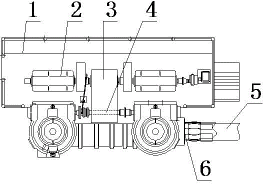
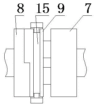
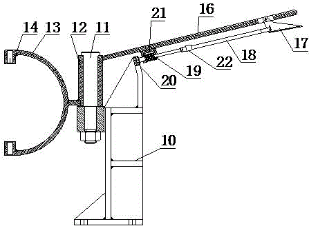
[0022] Specific implementation methods: such as Figure 1-Figure 3 As shown, a part structure of the blanking machine that adopts the clutch device of the present invention includes a pressing motor 2 arranged on the frame 1 above the upper roll, and the output end of the pressing motor 2 is connected to the pressing speed reducer 3. The lower speed reducer 3 has an output shaft 4 arranged in parallel above the upper roller 6, and both ends of the output shaft 4 of the reduction speed reducer extend out of the speed reducer housing and form two power output ends for depression, and two power output ends for depression Each is connected through a steering connection transmission pair and a nut transmission connection. The nuts are respectively matched on a vertically arranged screw rod to form a screw nut transmission pair, which can drive the screw rod to move up and down. The screw rod is vertically arranged on the upper The position above the two ends of the roll 6 and the l...


PUM


Abstract

The invention discloses a clutch device for regulation of an upper roller of a roughing mill. The clutch device comprises an input disc, an output disc and a clutch disc, wherein the input disc is connected with the pressure power output end of a pressure speed reducer of the roughing mill; the output disc is connected with a transmission pair which is in steering connection above the end part of the upper roller of the roughing mill; the clutch disc is positioned between the input disc and the output disc. The clutch device also comprises a shifting device which is connected with the clutch disc and is used for shifting the clutch disc in the axial direction to realize engagement and disengagement. The invention also discloses a regulating method of the upper roller of the roughing mill; the regulating method adopts the clutch device, and one end of the clutch device is disconnected when the upper roller of the roughing mill moves upwards, so that the balance of the clutch device is restored again. The clutch device disclosed by the invention has the advantages that the structure is simple, the mechanical control can be realized, and the operation is convenient and reliable; meanwhile, through the regulating method realized on the basis of the clutch device, the horizontal regulating method of the upper roller can be conveniently and quickly realized, so that the job smoothness of the roughing mill is improved, and the production efficiency is improved.

Description

technical field [0001] The invention relates to a blanking machine used in steelmaking equipment; in particular, it relates to a clutch device for adjusting rolls on the blanking machine and an adjusting method thereof. [0002] Background technique [0003] The blanking machine is the equipment connected to the exit of the heating furnace in the steelmaking equipment, which is used to shape the billet of the rolled piece coming out of the heating furnace and remove the oxide scale on the surface of the billet, which can roll the billet into the required shape , size, structure and performance, so that the rolling mill can bite into it. [0004] The billet opening machine structure generally includes a frame, a lower roll fixedly installed on the frame and an upper roll horizontally arranged above the lower roll. The upper end of the upper roll is provided with a pressing part structure, wherein the pressing part structure includes The pressing motor on the frame, the outp...

Claims


Application Information

Patent Timeline
Patent Type & Authority Applications(China)
IPC IPC(8): B21B31/16F16D11/04B21D1/02B21D3/02B21B45/04
Inventor 李兴杰代晓斌陈东升陈旭柳岸赵瑾淄蒋宏
Owner CHONGQING IRON & STEEL CO LTD
Why Eureka
Try Eureka