
A method for generating a driving waveform of a thyristor rectifier and its driving circuit

A technology of thyristor driving and driving waveforms, which is applied in the direction of electrical components, output power conversion devices, AC power input conversion to DC power output, etc., can solve the problems of PWM waveforms not being synchronized, delay errors, etc., to improve working accuracy and Work stability, precise on-time control, high-precision wave effect

Inactive Publication Date: 2017-05-03
SHENZHEN JINGFUYUAN TECH
View PDF3 Cites 0 Cited by
  • Summary
  • Abstract
  • Description
  • Claims
  • Application Information

AI Technical Summary

Problems solved by technology

[0004] The present invention aims to solve the technical problem that the PWM waveform and the reference sine wave cannot be synchronized in the prior art, and there is a delay error between the actual interrupted wave generation time and the zero-crossing time of the AC sine wave voltage, and provides a thyristor rectifier driving waveform generation method to realize high-precision wave generation of PWM waveform

Method used


Image

  • A method for generating a driving waveform of a thyristor rectifier and its driving circuit
  • A method for generating a driving waveform of a thyristor rectifier and its driving circuit
  • A method for generating a driving waveform of a thyristor rectifier and its driving circuit

Examples


Embodiment Construction

[0042] In order to make the technical problems, technical solutions and beneficial effects solved by the present invention clearer, the present invention will be further described in detail below in conjunction with the accompanying drawings and embodiments. It should be understood that the specific embodiments described here are only used to explain the present invention, not to limit the present invention.

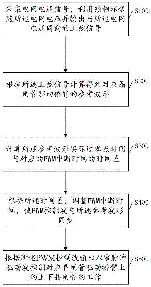
[0043] The drive signal of the thyristor generally has two forms, one is wide pulse trigger, and the other is double narrow pulse trigger. In the present invention, a wide pulse trigger signal is generated by a DSP, and a double narrow pulse driving signal can be generated after being combined by a CPLD. The specific embodiments are as follows figure 1 As shown, the present invention provides a method for generating a driving waveform of a thyristor rectifier, comprising:

[0044] Step S100, collecting a grid voltage signal, using a phase-locked loop to follow the grid ...


PUM


Abstract

A generation method of the driving waveform of a thyristor rectifier comprises the following steps that power grid voltage signals are collected, and a phase-locked loop follows power grid voltage and outputs a sinusoidal signal the same with the power grid voltage in direction; a reference waveform corresponding to a thyristor drive bridge arm is obtained by calculation according to the sinusoidal signal; the difference between the actual zero time of the reference waveform and the corresponding PWM break time is calculated; according to the time difference, the PWM break time is adjusted, so that a PWM control wave and the reference waveform are synchronous; according to the PWM control wave, a double-narrow pulse drive wave is output to control upper and lower thyristors on the corresponding thyristor drive bridge arm to work. According to the scheme, high-precision PWM control wave emission is achieved, breakover time control on the thyristors is more accurate, and working precision and stability of the thyristor rectifier are improved effectively.

Description

technical field [0001] The invention belongs to the field of electronic circuit control, and in particular relates to a method for generating driving waveforms of a thyristor rectifier and a driving circuit thereof. Background technique [0002] In industrial production, thyristor rectifiers are widely used in AC variable-speed soft-start systems, especially in high-power applications, and their performance directly affects the operating indicators of the system. The driving signal generation circuit is the core control part of the three-phase thyristor circuit. The analog pulse trigger used in the traditional thyristor rectification or inverter system uses multiple analog devices, and the device parameters are scattered. Not only is it inconvenient to debug and use, but also the generated The pulse symmetry is poor, and the analog signal directly controls the pins of the chip, so the interrupt working mode cannot be used, because the interrupt will interrupt the analog wave...

Claims


Application Information

Patent Timeline
Patent Type & Authority Patents(China)
IPC IPC(8): H02M1/08
CPCH02M7/1626
Inventor 刘晓红陈恒留
Owner SHENZHEN JINGFUYUAN TECH
Learn More