
4G antenna with metal frame

A metal frame and 4G antenna technology, applied in the field of wireless communication, can solve the problems of small antenna space, limited antenna radiation, unfavorable antenna design of metal frame, etc., and achieve the effect of avoiding the deterioration of antenna performance and expanding the low-frequency bandwidth

Inactive Publication Date: 2015-01-21
HUIZHOU SPEED WIRELESS TECH CO LTD
View PDF4 Cites 57 Cited by
  • Summary
  • Abstract
  • Description
  • Claims
  • Application Information

AI Technical Summary

Problems solved by technology

[0003] Portable terminal products with metal texture are favored by consumers, but the metal frame is not conducive to the design of the antenna and limits the radiation of the antenna
Moreover, based on the requirements of styling, the thickness of mobile phones is getting thinner and thinner, the space for antennas is getting smaller and smaller, and the environment around the antennas is becoming more and more complicated.
Therefore, in a limited space and complex environment, it is necessary to integrate the metal frame, ensure the shape design requirements, and meet the multi-frequency antenna, which brings great challenges to the antenna design. The existing antenna technology is difficult Ensure that the antenna radiation quality can still meet the requirements when used on mobile terminal equipment with metal frames

Method used

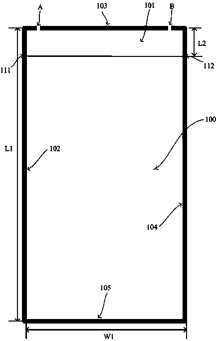

Image

  • 4G antenna with metal frame
  • 4G antenna with metal frame
  • 4G antenna with metal frame

Examples


Embodiment 1

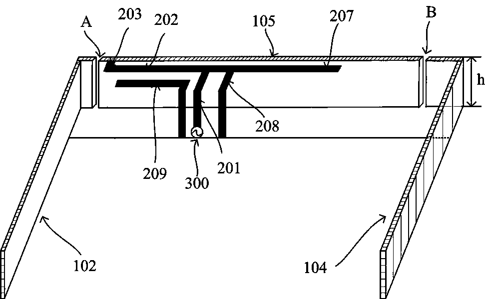
[0031] figure 2 It is a schematic diagram of the application state of Embodiment 1 of the metal frame 4G antenna of the present invention.

[0032] Such as figure 2 As shown, the antenna part includes a feed source 300 and an antenna trace part. In this embodiment 1, the feed source 300 leads upward to the feed trace, and when the feed trace extends to the top of the clearance area 101, it bends to the second The direction of the frame 103 continues to extend, and one end close to the second frame 103 extends in the opposite horizontal direction to high-frequency traces and low-frequency traces.

[0033] Wherein, the extended low-frequency wiring includes a first low-frequency branch 202 and a second low-frequency branch 203. One end of the first low-frequency branch 202 is connected to the feeder wiring, and the other end is connected to the second low-frequency branch 203. The second low-frequency branch 202 The direction 203 is perpendicular to the first low-frequency b...

Embodiment 2

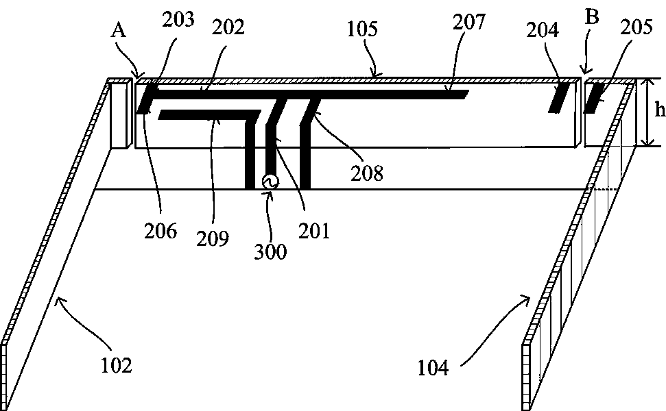
[0040] image 3 It is a schematic diagram of the application state of Embodiment 2 of the metal frame 4G antenna of the present invention.

[0041] Such as image 3 As shown, the antenna embodiment 2 is improved based on the antenna structure of embodiment 1,

[0042] The antenna part of Embodiment 2 includes a feed source 300 and an antenna trace part. The feed source 300 leads upward to the feed trace. When the feed trace extends to the top of the clearance area 101, it bends and continues to extend toward the second frame 103. A high-frequency trace and a low-frequency trace extend horizontally from one end close to the second frame 103 .

[0043] Compared with Embodiment 1, the antenna radiation principle is basically the same, but considering that the application environment of different terminal equipment antennas will be different, the following improvements are made to Embodiment 1:

[0044] A fourth low-frequency branch 204 is provided. When the second high-frequen...


PUM


Abstract

A 4G antenna with a metal frame comprises the metal frame, a PCB and an antenna part. The PCB comprises a clearance area and a metal area, the antenna part is located in the clearance area, and comprises a feed supply, a grounding point and a line part, the grounding point and the feed supply are arranged on the PCB, the grounding point is connected with the metal area, a feed line is led out of the feed supply, and the feed supply horizontally extends from the end, close to the metal frame, of the feed line to form a high-frequency line and a low-frequency line which are opposite in direction. First low-frequency resonance is generated by a first low-frequency branch, a second low-frequency branch and a second frame body. First high-frequency resonance is generated by the first low-frequency branch, the second low-frequency branch and a first frame body radiation loop. A first high-frequency branch and the second frame body are coupled to generate second high-frequency resonance. A parasitic branch is used for generating third high-frequency resonance. The method that the front part of the low-frequency line is bent in the reverse height direction is utilized, and the low-frequency bandwidth of the antenna is expanded. Each high-frequency resonance is generated by the radiation of the metal frame, and the problem that the metal frame shields high-frequency antenna radiation is solved.

Description

technical field [0001] The invention relates to the field of wireless communication, in particular to a metal frame 4G antenna. Background technique [0002] The bandwidth expansion of mobile terminal antennas has always been the development direction of mobile terminal communications, especially portable mobile terminals, 3G has become the current mainstream, and its frequency bandwidth is 824-960MHz and 1710-2170MHz. With the application of LTE technology, the low frequency requires a bandwidth of 704MHz-960MHz, and the high frequency requires a bandwidth of 1710-2700MHz. The rapid increase in bandwidth brings difficulties to antenna design. [0003] Portable terminal products with metal texture are favored by consumers, but the metal frame is not conducive to the design of the antenna and limits the radiation of the antenna. Moreover, based on the requirements of styling, the thickness of mobile phones is getting thinner and thinner, the space for antennas is getting...

Claims


Application Information

Patent Timeline
Patent Type & Authority Applications(China)
IPC IPC(8): H01Q1/38H01Q1/48H01Q5/10
Inventor 罗文波吴永茂
Owner HUIZHOU SPEED WIRELESS TECH CO LTD
Learn More