Gas density relay free of detachment in verification process
A gas density, relay technology, applied in circuits, electrical switches, electrical components, etc., to achieve the effects of small size, good sealing performance, and high environmental protection value
- Summary
- Abstract
- Description
- Claims
- Application Information
AI Technical Summary
Problems solved by technology
Method used
Image
Examples
Embodiment 1
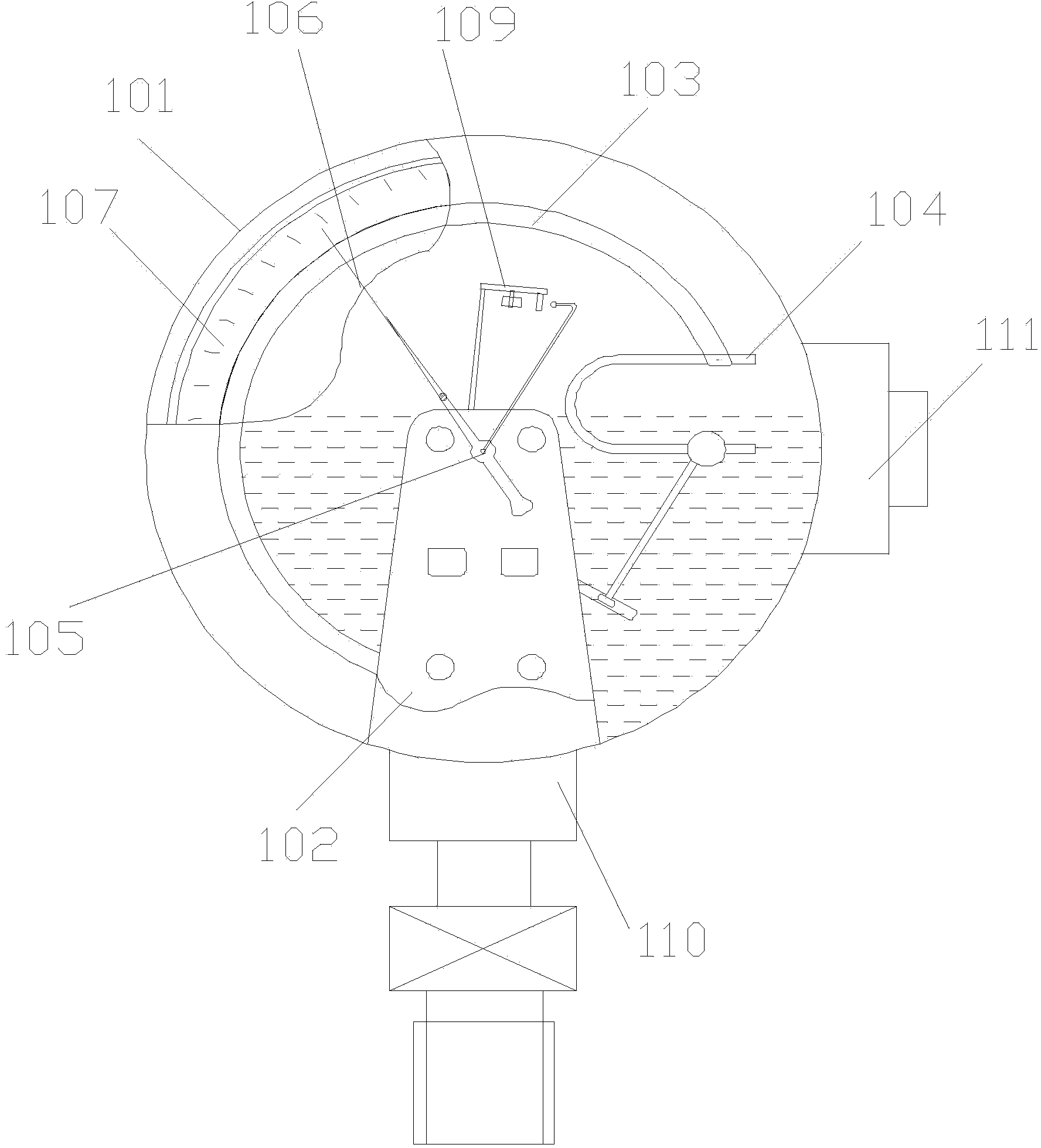
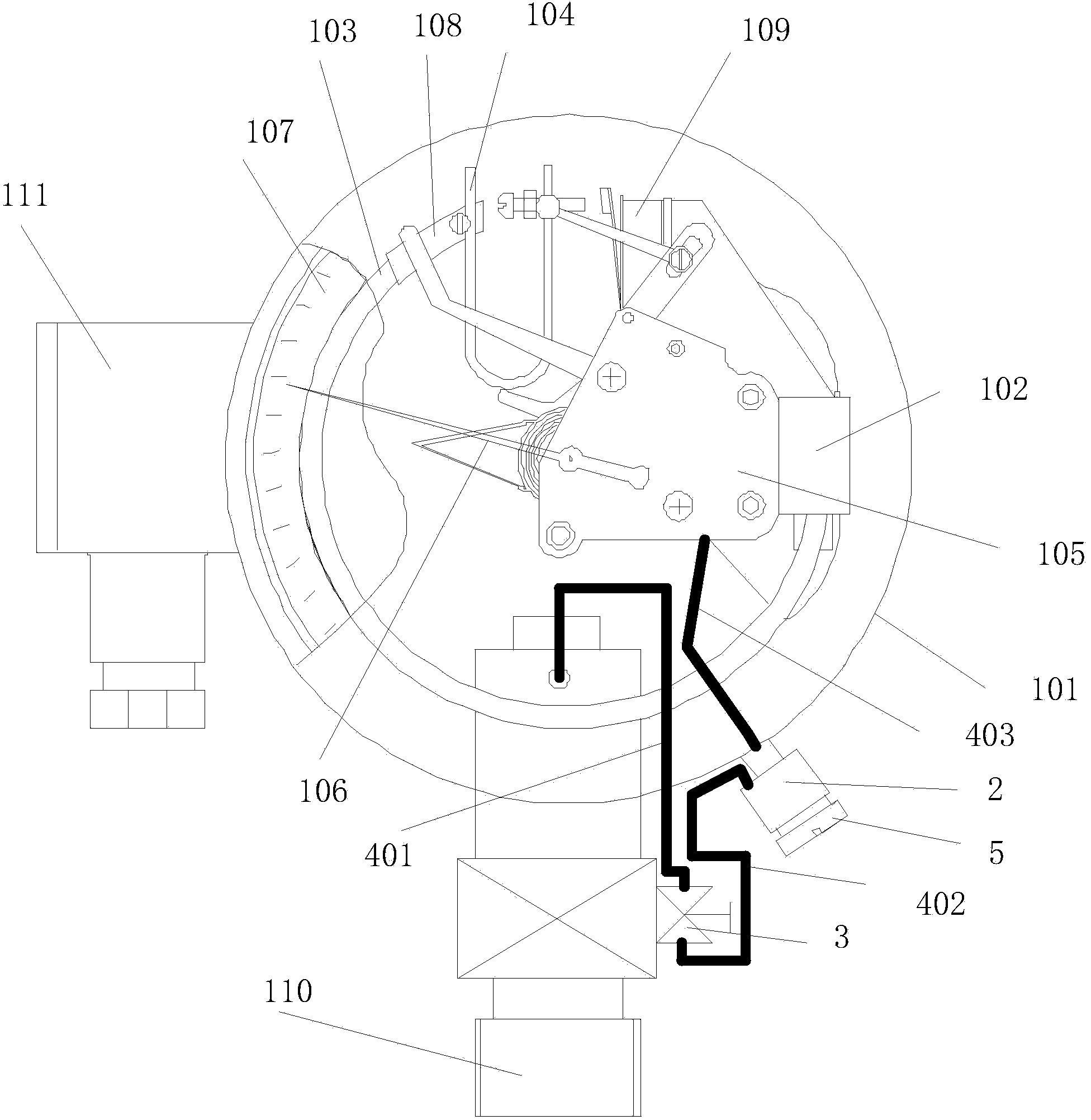
[0036] figure 2 It is a front view partial cross-sectional schematic diagram of a gas density relay according to Embodiment 1 of the present invention, such as figure 2 As shown, the disassembly-free gas density relay according to Embodiment 1 of the present invention includes: a housing 101, a base 102, a pressure detector 103, a temperature compensation element 104, and a core 105 disposed in the housing. , Pointer 106, Dial 107, End Block 108, Several Signal Generators 109, Equipment Connection Joint 110, and Verification Interface 2 and Valve 3. One end of the valve 3 communicates with the equipment connection joint 110, and the other end of the valve 3 communicates with the calibration port 2; the calibration port 2 communicates with the pressure detection port 2 through the base 102 Device 103 is connected. The verification interface 2 can be designed as a quick connection to further improve work efficiency.
[0037] Wherein, one end of the pressure detector 103 and...
Embodiment 2
[0040] image 3 It is a front view partial cross-sectional schematic diagram of a gas density relay according to Embodiment 2 of the present invention, such as image 3 As shown, the verification interface 2 is fixed on the lower right corner of the housing 101 of the gas density relay, that is, below the terminal block 111, the valve 3 of the gas density relay is arranged on the equipment connection joint 110 of the gas density relay, and the verification interface 2 is set on the casing 101. On the gas circuit, one end of the valve 3 is connected to the equipment connection joint 110, the other end of the valve 3 is connected to the calibration port 2 through the gas circuit connector 402 of the calibration port, and the calibration port 2 is connected to the gas circuit connector 403 of the relay. The base 102 and the pressure detector 103 are connected. When the valve 3 is opened, the equipment connection joint 110 is connected with the base 102 and the pressure detector...
Embodiment 3
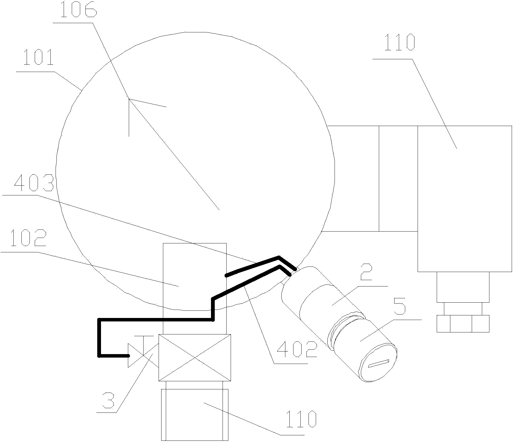
[0042] Figure 4 It is a front view partial cross-sectional schematic diagram of the gas density relay of Embodiment 3 of the present invention, as Figure 4 As shown, the verification interface 2 is fixed on the lower right corner of the housing 101 of the gas density relay, that is, below the wiring seat 111, the valve 3 of the gas density relay is arranged on the housing 101, and the verification interface 2 is arranged on the on the housing 101. On the air circuit, one end of the valve 3 communicates with the equipment connection joint 110 through the switch air circuit connector 401, and the other end of the valve 3 communicates with the calibration port 2 through the calibration interface gas circuit connector 402, and the calibration interface 2 passes through The relay air circuit connection part 403 communicates with the base 102 and the pressure detector 103 . When the valve 3 is opened, the equipment connection joint 110 is connected with the base 102 and the pres...
PUM
 Abstract
Description
Claims
Application Information
 - R&D
- Intellectual Property
- Life Sciences
- Materials
- Tech Scout
- Unparalleled Data Quality
- Higher Quality Content
- 60% Fewer Hallucinations
Browse by: Latest US Patents, China's latest patents, Technical Efficacy Thesaurus, Application Domain, Technology Topic, Popular Technical Reports.
© 2025 PatSnap. All rights reserved.Legal|Privacy policy|Modern Slavery Act Transparency Statement|Sitemap|About US| Contact US: help@patsnap.com


