Method to rotate the rotor of a wind turbine and means to use in this method

Active Publication Date: 2013-03-21
SIEMENS GAMESA RENEWABLE ENERGY AS
View PDF4 Cites 3 Cited by
  • Summary
  • Abstract
  • Description
  • Claims
  • Application Information

AI Technical Summary

Benefits of technology

The patent text describes a new method to save time and money when installing rotor blades on a wind turbine. By using a crane and other equipment, the rotor blades can be rotated into position without the need for a crane to move around. This means that less equipment is needed and there is less downtime for setting up the crane for each new rotor blade. Overall, this method saves time and money during wind turbine installation.

Problems solved by technology

This shows a disadvantage that there are no gravitational forces to support the rotation before the connection between the hub and the first rotor blade is established.
Thus the described method is not reliable enough to perform the rotation of the hub during the installation of the rotor blades.

Method used


Image

  • Method to rotate the rotor of a wind turbine and means to use in this method
  • Method to rotate the rotor of a wind turbine and means to use in this method
  • Method to rotate the rotor of a wind turbine and means to use in this method

Examples


Embodiment Construction

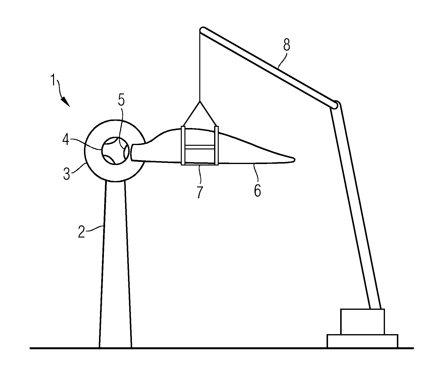
[0078]FIG. 1 shows the installation of a rotor blade at a wind turbine.

[0079]The direct driven wind turbine 1 comprises a tower 2, a generator 3 and a hub 4. The hub 4 comprises at least one place 5 where a rotor blade 6 is attached.

[0080]The rotor blade 6 is held by a lifting device 7 and is lifted by a crane 8. To attach the rotor blade 6 at the place 5 at the hub 4, the hub 4 needs to be turned in a certain predetermined position.

[0081]For the installation of a second rotor blade the hub has to be turned into a second position. By turning the hub into the predetermined positions the crane 8 can stay at the same place during the installation of all rotor blades 6.

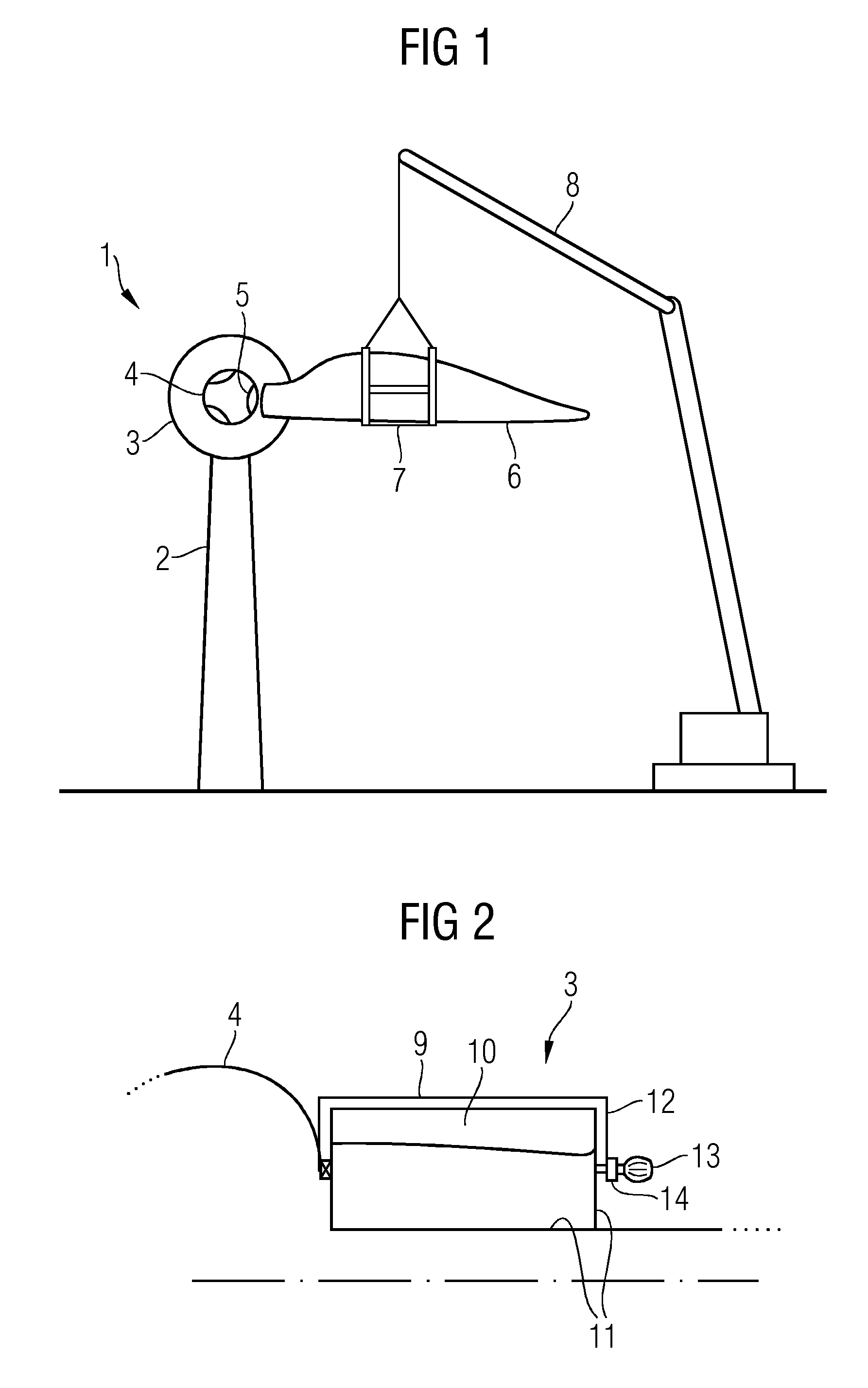
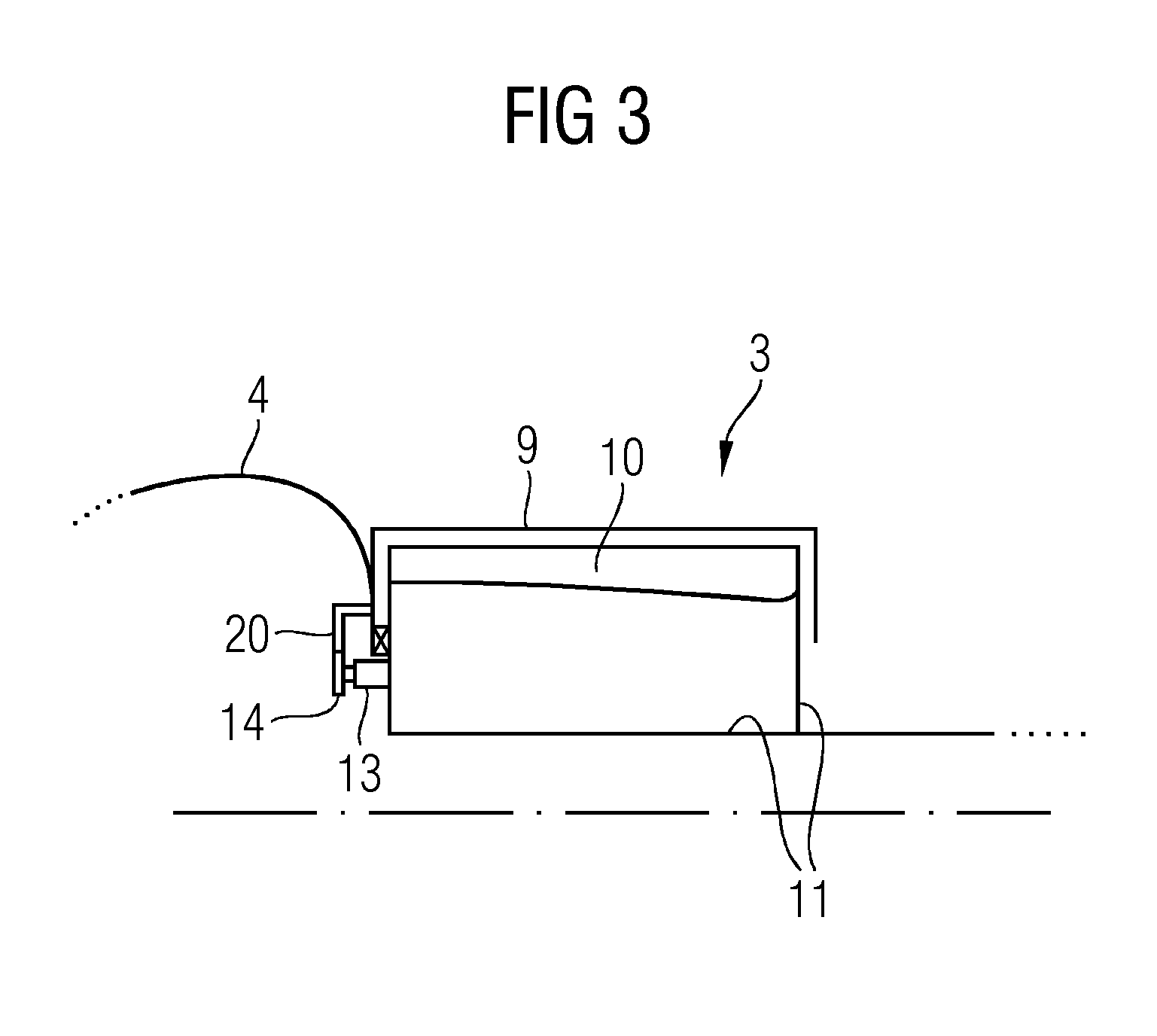
[0082]FIG. 2 shows the principle of a motor acting on the brake-disc.

[0083]FIG. 2 shows a cut through a generator 3 and a hub 4 of a direct driven wind turbine. The generator comprises a rotor 9 and a stator 10. The stator 10 is mounted to a support structure 11.

[0084]At the end of the rotor 9 of the generator 3, that is ...


PUM


Abstract

A direct driven wind turbine includes an electrical generator with a rotor and a stator, a hub constructed to receive a rotor blade, and an actuator device. The hub is connected to the rotor of the electrical generator. The hub and the rotor of the electrical generator are rotatable mounted in respect to the stator of the generator. The actuator device is constructed and arranged to rotate the rotor of the electrical generator and the hub of the wind turbine in respect to the stator of the electrical generator, wherein the actuator device is at least one motor.

Description

CROSS REFERENCE TO RELATED APPLICATIONS[0001]This application claims priority of European Patent Office application No. 11182200.3 EP filed Sep. 21, 2011. All of the applications are incorporated by reference herein in their entirety.FIELD OF INVENTION[0002]The illustrated embodiments relate to a method to rotate the rotor of a wind turbine and to a device to be used in this method.BACKGROUND OF INVENTION[0003]A wind turbine transfers the energy of the wind into electrical energy. The wind turbine comprises a nacelle that is connected to a tower and a rotor that is connected to the nacelle. The rotor comprises a hub that is rotatable mounted to the nacelle and at least one rotor blade mounted to the hub.[0004]The wind interacts with the rotor blade of the wind turbine in a way that the rotor rotates. The rotation of the rotor is transferred to an electrical generator.[0005]When the wind turbine is erected, the tower is set up and the nacelle is mounted onto the tower. The hub is mo...

Claims


Application Information

Patent Timeline
IPC IPC(8): F03D9/00
CPCF03D1/001F03D1/0658F05B2220/7066Y02E10/728Y02E10/721Y02E10/725F05B2230/60F03D13/10Y02E10/72Y02P70/50
Inventor FALKENBERG, PETER LOEVENSKJOLDMAJ, KARL AAGENIELSEN, JACOB BLACHPOULSEN, HENNINGRASMUSSEN, BRIANSTIESDAL, HENRIK
Owner SIEMENS GAMESA RENEWABLE ENERGY AS
Why Eureka
Try Eureka