
A slotted solid heat storage body structure

A solid heat storage, heat storage body technology, applied in heat storage equipment, heat exchanger types, indirect heat exchangers, etc., can solve problems such as blockage of air ducts, heat loss, increase, etc. The effect of the need for heat exchange

Active Publication Date: 2016-04-06
SHENYANG LANHAO NEW ENERGY TECH CO LTD +1
View PDF7 Cites 0 Cited by
  • Summary
  • Abstract
  • Description
  • Claims
  • Application Information

AI Technical Summary

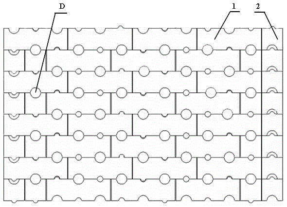
Problems solved by technology

At present, due to some defects in structural design and setting methods on the market, the heat storage body of the existing solid electric heat storage device absorbs heat and releases heat unevenly, which easily causes some electric heating elements to burn out due to excessive temperature. Blocking the air duct will increase the cost of the device due to the replacement of the heating wire element and affect its normal operation; and the design of the air duct of the heat storage body is unreasonable, so that the gas in the air duct expands with the increase of the temperature of the heat storage body, and the excess after expansion The gas will overflow from the connection of the air duct, causing part of the heat loss, thereby reducing the thermal efficiency of the whole machine

Method used


Image

  • A slotted solid heat storage body structure
  • A slotted solid heat storage body structure
  • A slotted solid heat storage body structure

Examples


Embodiment Construction

[0011] The present invention provides a slot-type solid heat storage body structure. In order to make the purpose, technical solution and effect of the present invention clearer and clearer, the present invention will be further described in detail below. It should be understood that the specific implementations described here are only used to explain the present invention, not to limit the present invention. The structure of the slot-type solid thermal storage body implemented according to the present invention will be described in detail below with reference to the accompanying drawings.

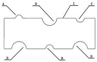
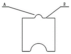
[0012] Referring to the accompanying drawings, a slot-type solid heat storage body structure includes a first heat storage brick body 1 and a second heat storage brick body 2. The heat storage body structure is composed of the first heat storage brick body 1 and the second heat storage brick body. A stack of 2 brick bodies, the first heat storage brick body 1 and the second heat storage br...


PUM


Abstract

The invention discloses a clamping groove type solid heat storage body structure in the field of energy conservation and environmental protection. The solid heat storage body structure comprises first heat storage brick bodies and second heat storage brick bodies, and is a stack body formed by stacking the first heat storage brick bodies and the second heat storage brick bodies, wherein adjacent heat storage brick layers are arranged in a staggered manner; the plurality of first and second heat storage brick bodies are arranged in each layer; a vent channel D used for heating or cooling is arranged on each of the first and second heat storage brick bodies; the vent channels of the first and second heat storage brick bodies in the same layer are communicated to form a through vent channel; an upper surface vent channel D is formed in the middle of the heat storage brick layer, and a clamping groove A and a clamping groove C are formed in the two sides of each upper surface vent channel D. According to the structure, two heat storage bricks are fastened to form a large round hole which is used for the penetration of a heating wire and serves as a heat exchange vent hole; convex and concave holes formed by fastening the two heat storage bodies are matched, so that the occlusion of the brick bodies is guaranteed and the overall stability of the heat storage body structure is ensured when the overall heat storage body structure is relatively high.

Description

technical field [0001] The invention relates to a slot-type solid heat accumulator structure in the field of energy saving and environmental protection. Background technique [0002] In recent years, with the rapid development of my country's energy-saving and environmental protection industry, solid-state electric thermal storage devices have been widely used in various industrial applications. Harmful gas emission, reduce environmental pollution. The key component in the regenerative heating chamber is the heat storage body, and the performance index and thermal efficiency of the solid heat storage device depend on the rationality of the heat storage body structure. At present, due to some defects in structural design and setting methods on the market, the heat storage body of the existing solid electric heat storage device absorbs heat and releases heat unevenly, which easily causes some electric heating elements to burn out due to excessive temperature. Blocking the air...

Claims


Application Information

Patent Timeline
Patent Type & Authority Patents(China)
IPC IPC(8): F28D20/00
CPCY02E60/14
Inventor 姜立兵郭振伟王洋张明远
Owner SHENYANG LANHAO NEW ENERGY TECH CO LTD
Learn More