Belt dragging skidding device

A belt and skid technology, which is applied in the field of belt dragging skid devices, can solve the problems of intermittent dragging process, wasteful replacement cost of the belt, bloated head part of the new belt, etc., and achieves simplified belt replacement operation steps and belt replacement steps. The effect of simplification and improved belt replacement efficiency

Active Publication Date: 2015-11-04
TONGLING MIRACLE MECHANICAL EQUIP
View PDF7 Cites 0 Cited by
  • Summary
  • Abstract
  • Description
  • Claims
  • Application Information

AI Technical Summary

Problems solved by technology

Sufficient belt joint length must be reserved before use, and this part must be cut off later to ensure the integrity of the belt body. Not to mention the cumbersome work steps, there is also the phenomenon of belt waste and increased replacement costs.
However, in the latter belt-tying towing method, the binding effect cannot be guaranteed, and slipping between the belt and the wire rope is often prone to occur during the towing process; once slipping, it needs to be tied again to continue towing, which seriously affects production efficiency
In addition, when the steel wire rope is wrapped around the new belt, it will inevitably lead to the extremely bloated head of the new belt, which often causes jamming when the belt travels in the narrow gap between the idler and the idler during the towing overload. Intermittent, which brings great trouble to the on-site operators

Method used


Image

  • Belt dragging skidding device
  • Belt dragging skidding device
  • Belt dragging skidding device

Examples


Embodiment Construction

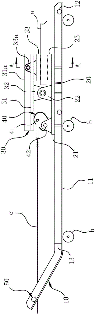
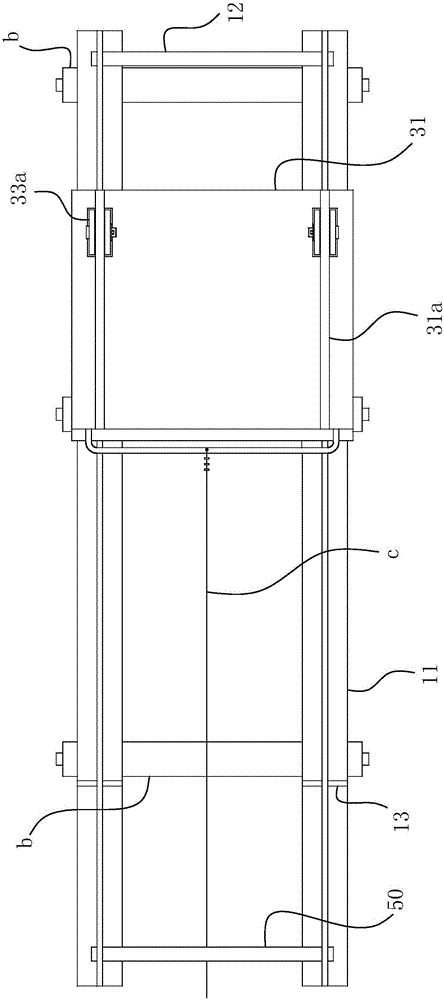
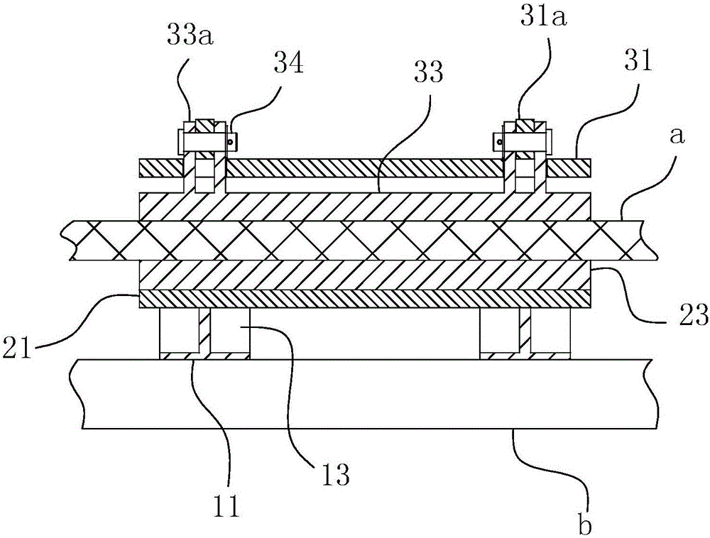
[0032] For ease of understanding, combined here Figure 1-3 The specific implementation structure and work flow of the present invention are described as follows:

[0033] The invention as Figure 1-3 As shown, it includes: a movable jaw bracket 30 with a hinged part and a fixed jaw bracket 20, and the two brackets together form a jaw structure similar to a vise. The jaw is arranged on the underframe 10, so that it can slide on the idler rollers b of the belt conveyor along the laying path of the belt a by means of the underframe 10.

[0034]The movable jaw bracket 30 and the fixed jaw bracket 20 both include two plate bodies that constitute the movable jaw plate 31 and the fixed jaw plate 21 respectively, and the hinged ears 22 and the matching ears 32 protruding from the middle section between the two plate bodies constitute the above-mentioned vise occlusal structure. The fixed jaw plate 21 is directly welded on the underframe 10, and a fixed jaw block 23 is fixed on the...


PUM


Abstract

The invention relates to the field of belt dragging equipment used for installing a new belt or replacing an old belt for a belt conveyer, in particular to a belt dragging skidding device. The belt dragging skidding device comprises an underbed and an occlusal jaw; the occlusal jaw comprises a fixed jaw support fixed to the underbed and a movable jaw support in articulated fit with the fixed jaw support; occlusal surfaces are arranged at the same-end opposite faces of the fixed jaw support and the movable jaw support; with the articulated fit position of the two supports as the border, an eccentric cam is hinged to the other end, opposite to the occlusal surface, of the fixed jaw support and is fixedly connected with a hauling cable, and an interval exists between the fixed connection point and the articulated point; the maximum eccentric height of the eccentric cam is larger than the maximum interval between the articulated point and the fit position of the eccentric cam on the fixed jaw support. The belt replacement step is simplified while the device achieves non-loss dragging of a belt body, operation is concise and convenient, the field work intensity is low, and the belt replacement efficiency can be improved effectively.

Description

technical field [0001] The invention relates to the field of belt dragging equipment when a belt conveyor is newly installed or an old belt is replaced, in particular to a belt dragging sled device. Background technique [0002] During the use of the belt conveyor, the belt will inevitably wear out with the increase of the use time, which requires the replacement of the belt to extend the service life of the entire equipment. The current belt replacement operation is to directly punch a hole at the head of the new belt to facilitate the threading of the wire rope for dragging; or to wrap the entire belt head with a wire rope, and the other end of the wire rope is threaded sequentially along the belt to be installed. Set up and finally connect to an external power source before turning on the machine for the pulling operation of the new belt. In the above operation process, the former will inevitably damage the rubber surface at the belt head due to the existence of the head...

Claims


Application Information

Patent Timeline
Patent Type & Authority Applications(China)
IPC IPC(8): B25B27/00
Inventor 孟德方
Owner TONGLING MIRACLE MECHANICAL EQUIP
Why Eureka
Try Eureka