
Multistage plunger hydraulic sludge pump

A hydraulic and sludge pump technology, applied in the direction of variable displacement pump components, pump components, liquid fuel engines, etc., can solve the problems of high energy consumption and high power, and achieve low energy consumption, large flow, and shorten the feeding. effect of time

Inactive Publication Date: 2015-01-21
YANGZHOU SIQI ENVIRONMENTAL PROTECTION EQUIP CO LTD
View PDF7 Cites 8 Cited by
  • Summary
  • Abstract
  • Description
  • Claims
  • Application Information

AI Technical Summary

Problems solved by technology

[0003] Aiming at the problems of high power and high energy consumption of existing sludge pumps, the present invention provides a low-energy-consumption, high-efficiency multi-stage plunger hydraulic sludge pump

Method used


Image

  • Multistage plunger hydraulic sludge pump
  • Multistage plunger hydraulic sludge pump
  • Multistage plunger hydraulic sludge pump

Examples


Embodiment Construction

[0016] The present invention will be further described below in conjunction with accompanying drawing:

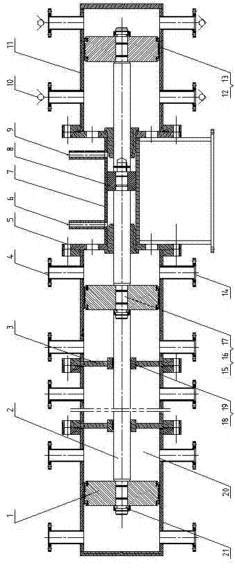
[0017] Such as figure 1 As shown, a multi-stage plunger hydraulic sludge pump consists of plunger 1, plunger rod 2, partition 3, sludge discharge port 4, connecting assembly 5, hydraulic oil inlet 6, power cylinder 7, column Plug 8, hydraulic oil outlet 9, one-way valve 10, single-stage working cylinder 11, sealing groove 12, sealing assembly 13, sludge inlet 14, stepped shaft 15, sealing groove 16, shaft sealing ring 17, sealing Groove 18, hole sealing ring 19, sludge chamber 20, fastener 21 constitute.

[0018] A multi-stage plunger hydraulic sludge pump, including a working cylinder and a power cylinder composed of a cylinder body and a plunger, is provided with at least one working cylinder 11 and a power cylinder 7, and the working cylinder 11 and a power cylinder 7 are connected by The assembly 5 is axially connected as a whole, and the plunger rods 2 of the plunge...


PUM


Abstract

The invention discloses a multistage plunger hydraulic sludge pump and belongs to the technical field of sludge pumps. The multistage plunger hydraulic sludge pump comprises working cylinders and a power cylinder, wherein each working cylinder is composed of a cylinder body and a plunger, the power cylinder is composed of a cylinder body and a plunger, the working cylinders and the power cylinder are axially connected into a whole through connecting components, plunger rods of the plungers of all the working cylinders and the plunger rod of the plunger of the power cylinder are connected to form a straight rod, each working cylinder is provided with two sludge feed inlets provided with one-way valves and two sludge discharge outlets provided with one-way valves, the power cylinder is provided with a hydraulic oil inlet and a hydraulic oil outlet, the plunger of the power cylinder is pushed to make reciprocating motion through feeding and discharging of hydraulic oil, and the plungers in the working cylinders are driven to make reciprocating motion at the same time. By means of a multistage cylinder formed by connection of multiple single-stage working cylinders, the continuous process that discharging and feeding are conducted through multiple discharge outlets and multiple feed inlets at the same time is achieved, high flow can be realized with a small pipe diameter, feeding time is shortened, and feeding efficiency and discharging efficiency are improved.

Description

technical field [0001] The invention relates to the field of an energy-saving sludge pump, in particular to a low-pressure, high-flow multistage plunger hydraulic sludge pump suitable for sludge treatment construction. Background technique [0002] At present, in the process of sludge treatment, the feed pumps of the sludge dewatering machine include: plunger pumps, diaphragm pumps, screw pumps, vane pumps, gear pumps, etc.; screw pumps are small in size, simple in structure, and can pump high viscosity. The medium with poor fluidity has no shear, no agitation, no turbulent pulsation, and smooth pumping. It is widely used in the feed pump of the sludge dewatering machine; but its wear resistance is poor, the pressure loss is large, and the maintenance frequency is high. , Especially in high-pressure operation, the stator is easy to wear and lose pressure, and the flow rate is small, the power is large, and the energy consumption is high, so the operating cost of the screw pu...

Claims


Application Information

Patent Timeline
Patent Type & Authority Applications(China)
IPC IPC(8): F04B53/16
Inventor 杨开平
Owner YANGZHOU SIQI ENVIRONMENTAL PROTECTION EQUIP CO LTD
Learn More