
Radiator and control method thereof

A control method and radiator technology, applied in the control of coolant flow, machine/engine, engine components, etc., can solve problems such as unfavorable energy saving, engine differentiation, and inability to accurately control heat dissipation

Active Publication Date: 2017-09-12
LONGKOU ZHONGYU THERMAL MANAGEMENT SYST SCIAND TECH
View PDF2 Cites 0 Cited by
  • Summary
  • Abstract
  • Description
  • Claims
  • Application Information

AI Technical Summary

Problems solved by technology

The traditional control method of vehicle radiator is a kind of extensive control method, it is only for the purpose of not "boiling" the engine, it does not distinguish between different working conditions of the engine, and cannot accurately control heat dissipation, so it cannot effectively Solve the requirements of engine heating at low temperature and heat dissipation at high temperature
The power of the vehicle radiator comes from the engine, and the heat dissipation cannot be controlled according to the actual working conditions, which makes the traditional heat dissipation system increase unnecessary power consumption, which is not conducive to energy saving
On the other hand, the traditional vehicle radiator and its control method have also brought other problems, such as long-term operation of the fan. After a long period of operation, the radiator with only one large-diameter cooling fan is more prone to failure, that is, the failure rate On the other hand, the fan will make noise when it is running. Because the traditional vehicle radiator does not control the heat dissipation accurately, it does not distinguish the different working conditions of the engine, so the large-diameter fan can be used in various working conditions Under the condition of high rotation speed or heat dissipation without the need for heat dissipation, the noise of the fan is relatively high.

Method used


Image

  • Radiator and control method thereof
  • Radiator and control method thereof
  • Radiator and control method thereof

Examples


Embodiment 1

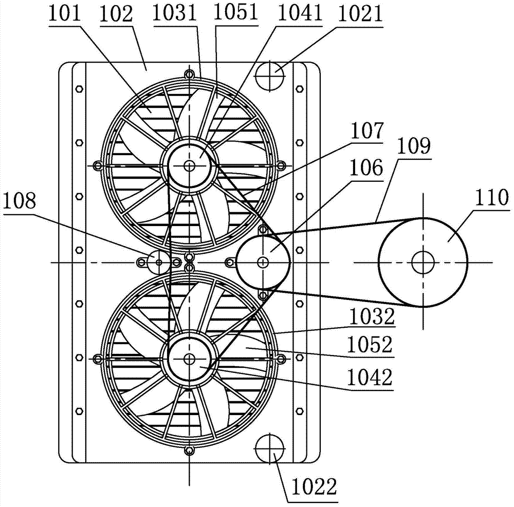
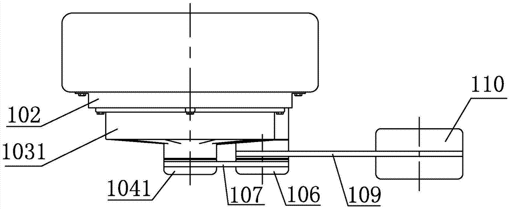
[0078] Such as figure 1 and figure 2 In the first embodiment of the radiator of the present invention shown, a water tank cover 102 is installed on the front side of the water tank 101, and the water tank cover 102 is provided with a water inlet 1021 and a water outlet 1022, and the water inlet 1021 and the water outlet 1022 are used for interspersed and The water inlet pipe and the water outlet pipe that the water tank 101 communicates, the first fan support 1031 and the second fan support 1032 are installed on the water tank cover 102, the first electromagnetic fan clutch 1041 is installed on the first fan support 1031, the first electromagnetic fan clutch 1041 The output end is fixedly connected with a first fan 1051, the second fan bracket 1032 is equipped with a second electromagnetic fan clutch 1042, the output end of the second electromagnetic fan clutch 1042 is fixedly connected with a second fan 1052, and the water tank cover 102 is also equipped with an electromagne...

Embodiment 2

[0100] The difference between the second embodiment of the radiator of the present invention and the first embodiment is that in this embodiment, the second electromagnetic fan clutch 1042 in the first embodiment is replaced by a three-speed clutch by a two-speed clutch. For the drawings of this embodiment, refer to the drawings of Embodiment 1.

[0101] Wherein the first control method of this embodiment includes the following steps:

[0102] Set the lower limit value T of the system 2min and upper limit T 2max ; at T 2min with T 2max Set two intermediate values ​​between T 2mid1 , T 2mid2 at T 2min with T 2max are divided into three intervals (T 2mid1 2mid2 );

[0103] When the tank temperature is lower than T 2min , control the electromagnetic switch clutch to be in the OFF position;

[0104] When the tank temperature is higher than T 2min and below T 2mid1 , control the electromagnetic switch clutch to be in the ON gear, control the first electromagnetic fan c...

Embodiment 3

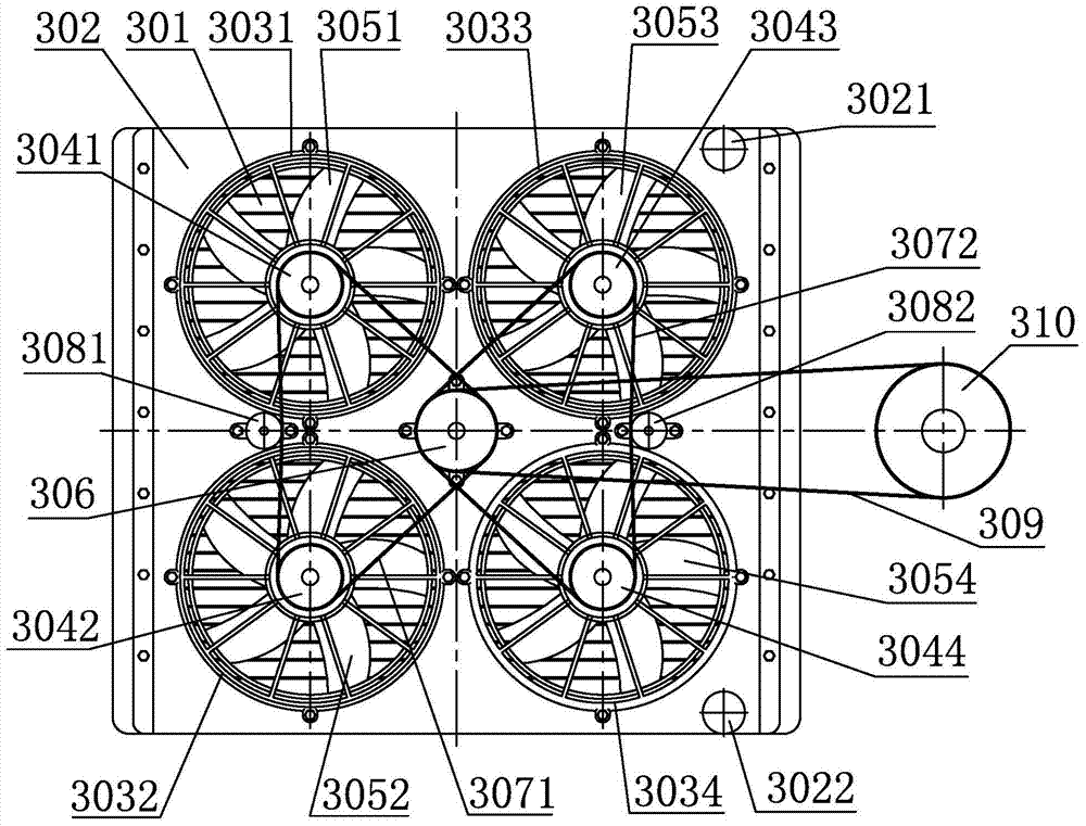
[0122] Such as image 3 and Figure 4In the third embodiment of the radiator of the present invention shown, a water tank cover 302 is installed on the front side of the water tank 301, and the water tank cover 302 is provided with a water inlet 3021 and a water outlet 3022, and the water inlet 3021 and the water outlet 3022 are used for interspersed and The water inlet pipe and the water outlet pipe that the water tank 301 is connected to, the first fan support 3031, the second fan support 3032, the third fan support 3033 and the fourth fan support 3034 are installed on the water tank cover 302, the first fan support 3031, the second fan support 3032, the third fan bracket 3033 and the fourth fan bracket 3034, the connecting line of the center of the four fan brackets is a square, the first fan bracket 3031 is equipped with a first electromagnetic fan clutch 3041, the output end of the first electromagnetic fan clutch 3041 A first fan 3051 is fixedly connected, a second elec...


PUM


Abstract

The invention relates to arrangement combined with cooling of a vehicle power device, in particular to a vehicle radiator. The invention further relates to a control method of the radiator. By means of the radiator, the heat dissipation capacity can be controlled precisely, the noise is lower, and the failure rate is lower. By means of the control method, the heat dissipation capacity can be controlled precisely, more energy is saved, and the noise is lower. The radiator comprises a switch clutch and at least two electromagnetic fan clutches. Input shafts of all the electromagnetic fan clutches are connected with an output shaft of the switch clutch through transmission devices. Output shafts of the electromagnetic fan clutches are connected with fans respectively. The total heat dissipation capacity of all the fans can be controlled by controlling the state of the switch clutch and the states of the electromagnetic fan clutches according to actual heat dissipation requirements, and the radiator and the control method can be applied to vehicle heat dissipation systems.

Description

technical field [0001] The present invention relates to an arrangement and a method in connection with the cooling of a vehicle power unit, in particular to a vehicle radiator. The invention also relates to a control method of the radiator. Background technique [0002] With the continuous development of the automobile industry, users' requirements for vehicle cooling systems are gradually developing in the direction of reliability, energy saving, precision and low noise. A traditional vehicle radiator dissipates heat through a large-diameter cooling fan driven by the engine through a pulley and a transmission belt. The traditional control method of vehicle radiator is a kind of extensive control method, it is only for the purpose of not "boiling" the engine, it does not distinguish between different working conditions of the engine, and cannot accurately control heat dissipation, so it cannot effectively Solve the requirements of heating up the engine at low temperature a...

Claims


Application Information

Patent Timeline
Patent Type & Authority Patents(China)
IPC IPC(8): F01P5/02F01P7/08F01P7/04
CPCF01P5/02F01P7/048F01P7/081
Inventor 王兆宇邢子义侯丰康
Owner LONGKOU ZHONGYU THERMAL MANAGEMENT SYST SCIAND TECH
Learn More