Wine tank with combined conveying tube
A combined, wine tank technology, applied in the field of winemaking, can solve the problems of increasing the production cost of the enterprise, reducing the efficiency of the wine tank, increasing the production cost, etc., and achieving the effects of improving efficiency, convenient pipeline and saving consumption.
- Summary
- Abstract
- Description
- Claims
- Application Information
AI Technical Summary
Problems solved by technology
Method used
Image
Examples
Embodiment 1
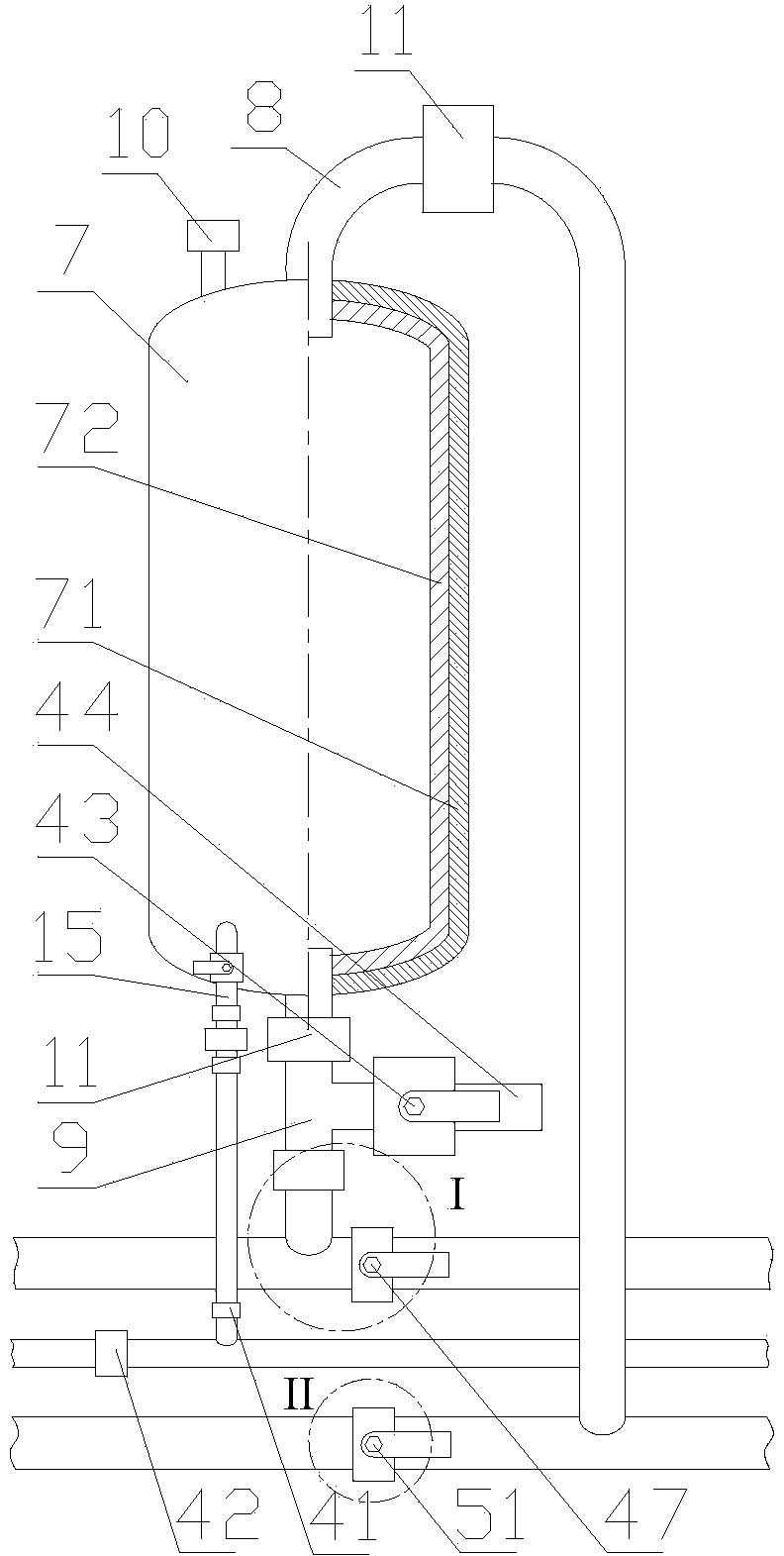
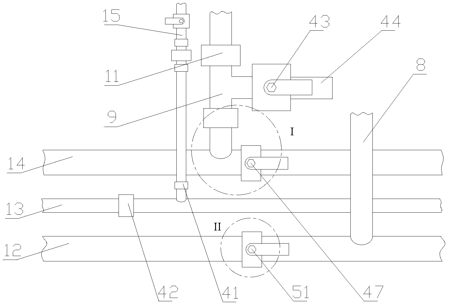
[0027] A wine tank with combined conveying pipe fittings includes a tank body 7 and combined conveying pipe fittings. The tank body 7 can adopt a single-wall structure or a double-wall structure. In this embodiment, the tank body 7 adopts a double wall structure, which includes an outer wall 71 and an inner wall 72, the outer wall 71 is a metal layer made of stainless steel, and the inner wall The body 72 is a clay layer fired from clay, and the inner wall body 72 is nested in the outer wall body 71 . The inner wall body 72 is a pottery clay layer fired from pottery clay. The pottery clay adopts non-toxic Nixing pottery clay. In the stainless steel outer wall body 71, such a design is beneficial to maintain the mouthfeel of the wine body, which is simple and practical.
[0028] The combined delivery pipe includes a wine inlet supervisor 12 , a wine outlet supervisor 14 , an aeration supervisor 13 and an aeration branch pipe 15 . One end of the wine inlet main pipe 12 communi...
Embodiment 2
[0031] On the basis of Embodiment 1, an electromagnetic flow control valve 11 is connected to the wine inlet pipe 8 and the wine outlet pipe 9 , and an electromagnetic ventilation valve 10 is provided on the top of the tank body 7 . By installing electromagnetic flow control valves 11 on the wine inlet pipe 8 and wine outlet pipe 9, when the wine reaches the set height, the electromagnetic flow control valve 11 on the wine inlet pipe 8 cannot be opened, and no more wine can be added to the tank. , to prevent overflow from the tank, at this time, the electromagnetic flow control valve 11 on the wine outlet pipe 9 can be opened, and the wine outlet operation can be performed; when the wine is lower than the set height, the electromagnetic flow control valve 11 on the wine outlet pipe cannot be opened , Can not carry out the wine operation, this moment, the electromagnetic flow control valve 11 on the wine inlet pipe 8 can be opened, can add wine in the jar.
Embodiment 3
[0033] On the basis of Embodiment 1 or Embodiment 2, the wine inlet main pipe 12 is provided with a first on-off valve 51, and the two ends of the first on-off valve 51 pass through the fifth hoop 50, the sixth hoop 52 and the wine inlet main pipe. 12 connections. Since a plurality of wine inlet pipes 8 are connected to one wine inlet main pipe 12 at the same time, multiple first switching valves 51 can be set on the wine inlet main pipe 12, and a first switch can also be set at the inflow end of the wine inlet main pipe 12. Valve 51.
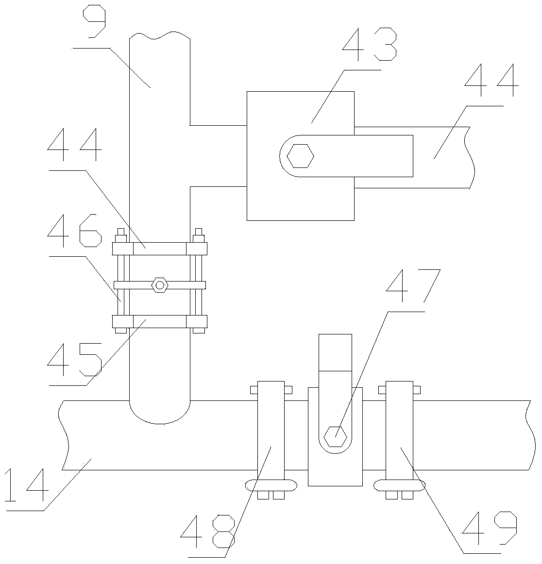
[0034] The wine outlet main pipe 14 is provided with a second on-off valve 47, and the two ends of the second on-off valve 47 are connected to the wine outlet main pipe 14 through the seventh hoop 48 and the eighth hoop 49 respectively. Since a plurality of wine outlet pipes 9 are connected to one wine outlet main pipe 14 at the same time, multiple second switch valves 47 can be set on the wine outlet main pipe 14, and a second switch can also...
PUM
 Abstract
Description
Claims
Application Information
 - R&D
- Intellectual Property
- Life Sciences
- Materials
- Tech Scout
- Unparalleled Data Quality
- Higher Quality Content
- 60% Fewer Hallucinations
Browse by: Latest US Patents, China's latest patents, Technical Efficacy Thesaurus, Application Domain, Technology Topic, Popular Technical Reports.
© 2025 PatSnap. All rights reserved.Legal|Privacy policy|Modern Slavery Act Transparency Statement|Sitemap|About US| Contact US: help@patsnap.com


