Material distributing mechanism of LED light splitting machine

A technology of a material separation mechanism and a spectroscope, which is used in sorting and other directions, can solve the problems of loss of parts such as the rotating shaft drive motor of the material separation head, unstable operation of the equipment, complicated installation structure, etc. The effect of stable operation and simple installation structure

Inactive Publication Date: 2014-12-17
广东志成华科光电设备有限公司
View PDF5 Cites 0 Cited by
  • Summary
  • Abstract
  • Description
  • Claims
  • Application Information

AI Technical Summary

Problems solved by technology

[0004] In the prior art, most of the distributing mechanism adopts two driving devices to realize the displacement in the XY direction. For example, the Chinese invention patent (patent number: 201010282640.8) discloses a distributing mechanism. In its technical solution, the distributing head transmission device includes The driving motor of the distributing head rotating shaft that drives the distributing head rotating shaft and the driving motor of the transmission rotating shaft driving the transmission rotating shaft realize the movement in the XY direction. On the rotating shaft, the driving motor of the rotating shaft of the distributing head vibrates continuously through the action of the rotating shaft of the transmission, and as the number of chips to be distributed increases, the speed of the rotating shaft of the transmission increases, and the rotation of the distributing head The greater the vibration caused by the shaft drive motor, the greater the loss of parts such as the rotary shaft drive motor of the distribution head, the high failure rate, and the unstable operation of the equipment. Moreover, the installation structure is complicated, and the accuracy of the parts needs to be repeatedly adjusted. , long assembly time, affecting production efficiency

Method used


Image

  • Material distributing mechanism of LED light splitting machine
  • Material distributing mechanism of LED light splitting machine

Examples


Embodiment Construction

[0034] The invention will be further described in detail below in conjunction with the embodiments and accompanying drawings, but the embodiment of the invention is not limited thereto.

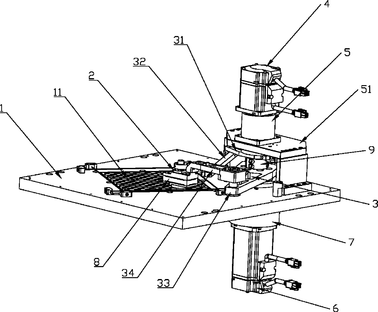
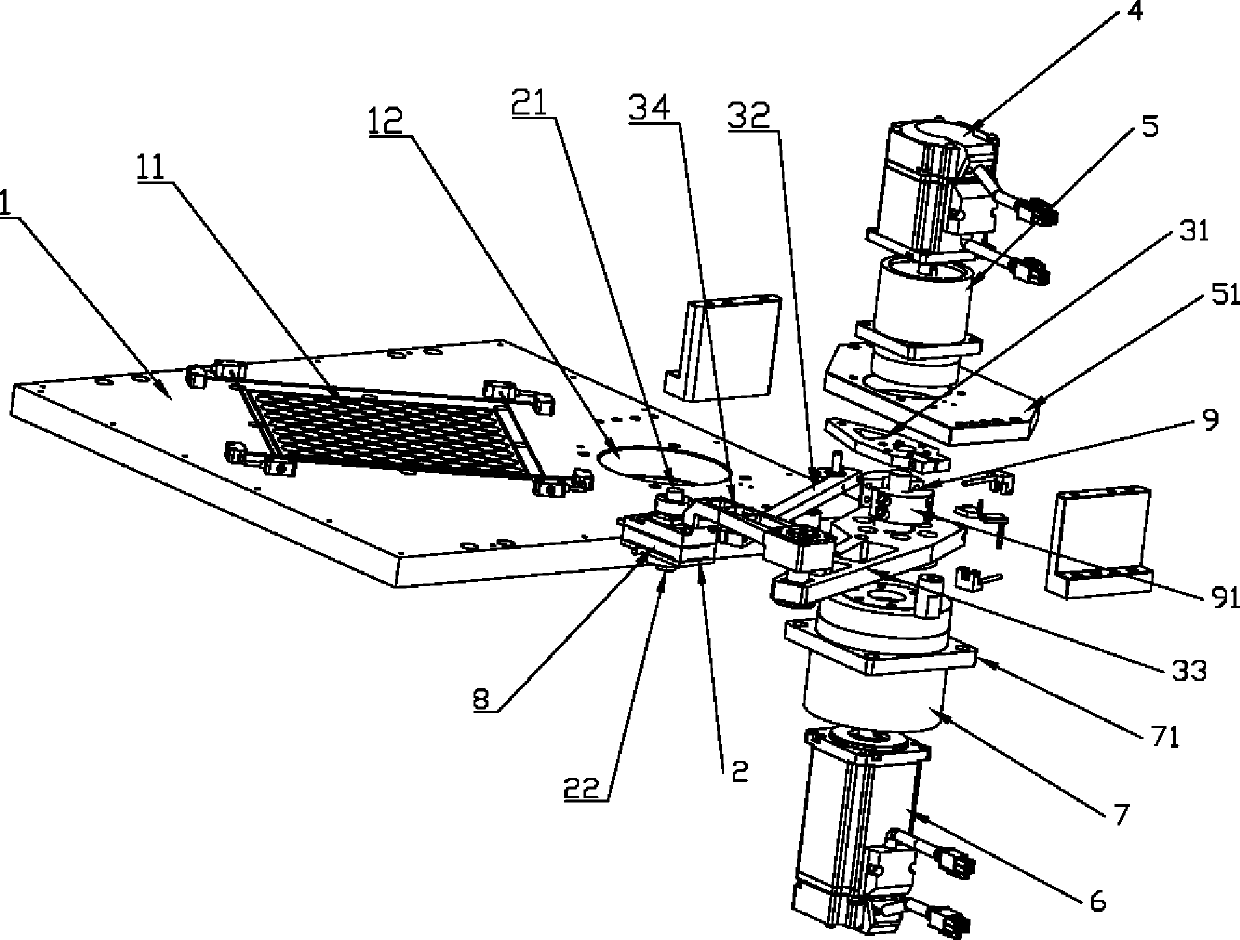
[0035] The specific embodiment of the material distributing mechanism of the invented LED spectrometer is as follows: figure 1 and figure 2 As shown, the material distribution bottom plate 1 is included, and the material distribution bottom plate 1 is provided with a plurality of material distribution holes 11, and each material distribution hole 11 is connected to a correspondingly classified material holding pipe;

[0036] The distributing mechanism also includes a four-bar mechanism 3, a distributing head device 2 connected to the four-bar mechanism 3, and a driving device that drives the four-bar mechanism 3 to move on the XY plane on the material distribution base plate 1, see figure 1 As shown, the XY plane is figure 1 The plane where the middle distribution hole 1 is located.

...


PUM


Abstract

The invention relates to the technical field of an LED (Light-Emitting Diode) light splitting machine, in particular to a material distributing mechanism of the LED light splitting machine. The material distributing mechanism comprises a material distributing baseplate, a four-bar mechanism, a material distributing head device and a driving device, wherein the material distributing head device is connected with the four-bar mechanism, and the driving device is used for driving the four-bar mechanism to do XY plane movement on the material distributing baseplate. The material distributing baseplate is provided with a mounting hole, and the driving device is arranged in the mounting hole. Compared with the prior art, the material distributing mechanism uses the driving device to drive the four-bar mechanism to cause the material distributing head device to do the XY plane movement, so that the material distribution of LED chips can be rapidly and precisely realized; a driving motor is arranged at the material distributing baseplate, when the driving motor and a transmission motor work at the same time, the driving motor and the transmission motor cannot mutually generate vibration, the loss and the faults of equipment caused by motor vibration can be prevented, and the equipment operation is more stable; and the mouting structure is simple, the material distributing mechanism is easily assembled, and the production efficiency can be greatly increased.

Description

Technical field [0001] The present invention involves the field of LED lighting machine technology, and it involves a sub -ingredient mechanism that specializes in a LED spathening machine. Background technique [0002] Patch emitting diode (LED) is a new type of surface -style installed semiconductor luminous device. It has the advantages of small volume, large scattered angle, and good luminous uniformity.superior. [0003] Because LED packaging needs to be split -to -color before the factory is out of the factory, the LED chip is classified (BIN) according to different parameters, and the LED spatsory machine is a device for online classification of LEDs, including the material division mechanism for the material for the material, for it for for the material for the material, for it for the material for the material for the material for the material for the material, which is used for the material for the material, which is used for the material for the material.Different LED ...

Claims


Application Information

Patent Timeline
Patent Type & Authority Patents(China)
IPC IPC(8): B07C5/36
Inventor 吴涛李斌
Owner 广东志成华科光电设备有限公司
Why Eureka
Try Eureka