
A rubber mixing and stirring device

A technology for mixing and mixing rubber, which is applied in the field of mixing devices and rubber mixing and stirring devices. It can solve the problems of low work efficiency, heavy rubber quality, and heavy cover plate quality, and achieve the effects of simple structure, improved efficiency, and reduced labor intensity.

Inactive Publication Date: 2016-08-10
广州连达橡塑有限公司
View PDF5 Cites 1 Cited by
  • Summary
  • Abstract
  • Description
  • Claims
  • Application Information

AI Technical Summary

Problems solved by technology

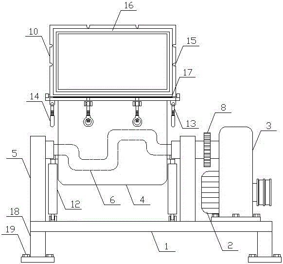
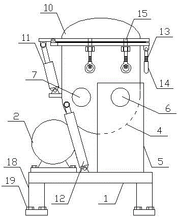
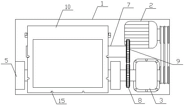
In the whole processing technology of rubber, it is necessary to mix rubber with different properties evenly, so that the mixed rubber has various characteristics. After the rubber is made into a product, the product can adapt to various needs. The existing rubber mixing Generally, a variety of rubbers are placed in the stirring tank manually in proportion, and the rubber is stirred and mixed evenly in the form of mechanical stirring. When the rubber is mixed and stirred, various rubber additives need to be put in. The cover of the existing rubber stirring tank The plate is generally opened and closed manually, the quality of the cover plate is heavy, and the labor intensity of the workers is relatively high. After the rubber is mixed and stirred, the existing mixing device generally needs to manually lift the rubber out of the stirring tank, and the quality of the rubber is relatively high. heavy, the labor intensity of the workers is high, and the working efficiency of rubber mixing is low, which cannot meet the needs of production

Method used


Image

  • A rubber mixing and stirring device
  • A rubber mixing and stirring device
  • A rubber mixing and stirring device

Examples


Embodiment Construction

[0012] In order to further describe the present invention, the specific implementation of a rubber mixing and stirring device will be further described below in conjunction with the accompanying drawings. The following examples are explanations of the present invention and the present invention is not limited to the following examples.

[0013] Such as figure 1 As shown, a rubber mixing and stirring device of the present invention includes a main support 1 and a stirring mechanism, and the stirring mechanism is arranged on the main support 1 . The stirring mechanism of the present invention includes a stirring motor 2, a gearbox 3, a stirring tank 4 and a stirring shaft. The upper side of the main support 1 is vertically and symmetrically provided with a fixed support 5. The stirring shaft includes a main stirring shaft 6 and an auxiliary stirring shaft 7. The stirring shaft 6 and the auxiliary stirring shaft 7 are horizontally connected to the stirring tank 4 respectively, th...


PUM


Abstract

The invention discloses a rubber mixing and stirring device, belonging to the field of rubber machining equipment. The rubber mixing and stirring device comprises a main bracket and a stirring mechanism, wherein the stirring mechanism comprises a stirring motor, a speed changing box, a stirring kettle and stirring shafts; the stirring shafts comprise a main stirring shaft and a secondary stirring shaft; the output end of the stirring motor is in transmission connection with the input end of the speed changing box; the output end of the speed changing box is coaxially connected with the main stirring shaft; a driving chain wheel is in transmission connection with a driven chain wheel by a chain; a cover plate is arranged on the upper side of the stirring kettle; one side of the cover plate is hinged with the upper side of the stirring kettle; a cover plate hydraulic cylinder is arranged between the cover plate and the stirring kettle; a discharging hydraulic cylinder is arranged between the stirring kettle and a main bracket; a plurality of clamping mechanisms are uniformly arranged on the upper side of the stirring kettle; and each clamping mechanism comprises a clamping rod and a fixing ring. The rubber mixing and stirring device is simple in structure and can be used for rapidly and efficiently stirring a plurality of types of rubber, so that the rubber can be sufficiently and uniformly mixed; and materials can be rapidly discharged and the requirements of production are met.

Description

technical field [0001] The invention relates to a stirring device, in particular to a rubber mixing and stirring device, which belongs to the field of rubber mechanical processing equipment. Background technique [0002] At present, the rubber industry is one of the important basic industries of the national economy. It not only provides people with daily-use, medical and other light-industrial rubber products that are indispensable in daily life, but also supplies heavy industries and emerging The industry provides various rubber-made production equipment or rubber parts. There are many kinds of rubber products. Rubber is divided into natural rubber and synthetic rubber according to raw materials, and divided into block raw rubber, latex, liquid rubber and powder rubber according to the shape. Latex is rubber. Colloidal water dispersion, liquid rubber is an oligomer of rubber, which is generally a viscous liquid before vulcanization, and powder rubber is processed from late...

Claims


Application Information

Patent Timeline
Patent Type & Authority Patents(China)
IPC IPC(8): B29B7/18B29B7/26
Inventor 张峰
Owner 广州连达橡塑有限公司
Learn More