
Flexible high voltage direct current transmission project converter station and arrangement method thereof

A flexible DC transmission and converter station technology, applied in the output power conversion device, the conversion of AC power input to DC power output, the substation, etc. Effects of radiated interference, interference reduction, and electrical distance reduction

Active Publication Date: 2015-01-14
STATE GRID CORP OF CHINA +5
View PDF4 Cites 8 Cited by
  • Summary
  • Abstract
  • Description
  • Claims
  • Application Information

AI Technical Summary

Problems solved by technology

[0003] However, according to the technical characteristics of flexible DC engineering, the converter station is equipped with its unique bridge arm reactor unit and multi-level converter valve unit; in addition, it is equipped with smoothing reactors, converter transformers, and DC transfer switches consistent with traditional high-voltage DC , Control and protection system units, these equipment units will generate electromagnetic waves of different frequencies, which will interfere with the external environment of the building and adjacent equipment, and affect the flexible direct current transmission project

Method used


Image

  • Flexible high voltage direct current transmission project converter station and arrangement method thereof
  • Flexible high voltage direct current transmission project converter station and arrangement method thereof

Examples


Embodiment Construction

[0020] The present invention will be described in detail below in conjunction with the accompanying drawings and embodiments.

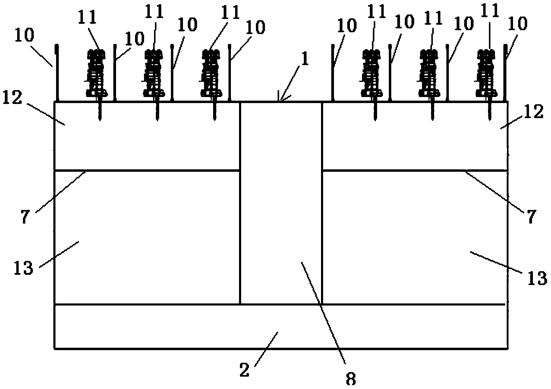
[0021] Such as figure 1 , figure 2 As shown, the present invention provides a flexible direct current transmission project converter station, which includes a combined building 1 , and the flexible direct current transmission project converter station is arranged in the combined building 1 . An indoor DC field 2 is installed on one side of the indoor side wall of the joint building 1, and the smoothing reactor unit 3 and the DC conversion switch unit 4 are installed in the indoor DC field 2. The longitudinal walls on both sides of the rest of the indoor space in the joint building 1 are respectively provided with functional rooms 7 for installing the bridge arm reactor unit 5 and the converter valve unit 6, and the control room 8 is set between the two functional rooms 7 to control and protect The system unit 9 is installed in the control room 8 . ...


PUM


Abstract

The invention relates to a flexible high voltage direct current transmission project converter station and an arrangement method of the flexible high voltage direct current transmission project convertor station. According to the arrangement method, a joint building is included, and the flexible high voltage direct current transmission project converter station is arranged inside the joint building; an indoor direct current field is arranged on a transverse wall on one indoor side of the joint building, smoothing reactor units and direct current change-over switch units are installed inside the indoor direct current field; longitudinal walls on the two sides of the rest indoor space of the joint building are each provided with a function room; each function room is composed of a bridge arm rector chamber and a valve hall; each bridge arm rector chamber is used for installing bridge arm rector units; each valve hall is used for installing converter valve units; a control room is arranged between the two function rooms, and control and protection system units are installed inside the control room; a roof, a floor and walls of the joint building are each provided with a metal shielding net and a firewall, so that a Faraday cage is formed. According to the flexible high voltage direct current transmission project converter station and the arrangement method of the flexible high voltage direct current transmission project converter station, electromagnetic radiation interference of all the equipment units inside the converter station can be prevented, and therefore the flexible high voltage direct current transmission project converter station and the arrangement method can be widely applied to the field of flexible high voltage direct current transmission.

Description

technical field [0001] The invention relates to a converter station and an arrangement method thereof, in particular to a flexible direct current transmission engineering converter station and an arrangement method thereof applied in the field of flexible direct current transmission. Background technique [0002] Traditional HVDC power transmission technology uses semi-controlled (self-conducting but not self-off) semiconductor devices (such as thyristors) for AC-DC conversion, and it needs to rely on the external voltage provided by the AC power system to assist in turning off the thyristors to ensure AC. DC conversion works normally. Flexible direct current transmission is a new type of direct current transmission technology other than traditional high voltage direct current transmission technology. ) for AC-DC conversion, flexible DC transmission technology can control active power and reactive power, and has no requirements for the strength of the AC system at both ends...

Claims


Application Information

Patent Timeline
IPC IPC(8): H02M7/00H02M1/44E04H5/04
CPCE04H5/04H02M1/44H02M7/003
Inventor 郑家松王赞常浩马为民石岩林国兴陈文兴乐波梅念陈东付颖程炜杜晓磊刘思源祝全乐李琦杨媛林玉烽曾静
Owner STATE GRID CORP OF CHINA
Learn More