
Microscopic system and microscopic method based on in-situ three-dimensional enhanced display

A microscope system and in-situ technology, applied in the field of microscopy, can solve the problems of difficulty in simultaneously ensuring user comfort and fusion image clarity, in-situ three-dimensional images, and small field of view, and achieve stereoscopic resolution. Fusion display, high-resolution stereo fusion display, and the effect of great operational flexibility

Inactive Publication Date: 2015-01-14
TSINGHUA UNIV
View PDF4 Cites 18 Cited by
  • Summary
  • Abstract
  • Description
  • Claims
  • Application Information

AI Technical Summary

Problems solved by technology

When the human eye observes a real object, the convergence and focus adjustment are consistent, but when viewing a stereoscopic image, the eye adjustment is on the screen, while the convergence is on the virtual stereoscopic image synthesized by parallax, so long-term viewing will inevitably lead to visual fatigue
[0004] It can be seen from the above that although the current microscopic system can directly observe the entity, the field of view is small, and it is difficult to perform in-situ enhanced display of 3D images; and although the head-mounted display can perform high-definition 3D image fusion, it is difficult to guarantee the user's accuracy at the same time. Comfort and fusion image clarity, easy to feel uncomfortable
At present, there is no microscopic display system that not only satisfies the in-situ enhanced display of three-dimensional stereoscopic images, but also ensures a sufficient field of view, and cannot provide users with real, intuitive, three-dimensional enhanced display of in-situ fused microscopic information

Method used


Image

  • Microscopic system and microscopic method based on in-situ three-dimensional enhanced display
  • Microscopic system and microscopic method based on in-situ three-dimensional enhanced display
  • Microscopic system and microscopic method based on in-situ three-dimensional enhanced display

Examples


Embodiment Construction

[0029] Embodiments of the present invention are described in detail below, examples of which are shown in the drawings, wherein the same or similar reference numerals designate the same or similar elements or elements having the same or similar functions throughout. The embodiments described below by referring to the figures are exemplary and are intended to explain the present invention and should not be construed as limiting the present invention.

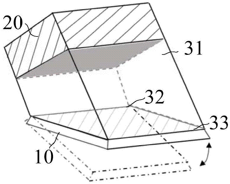
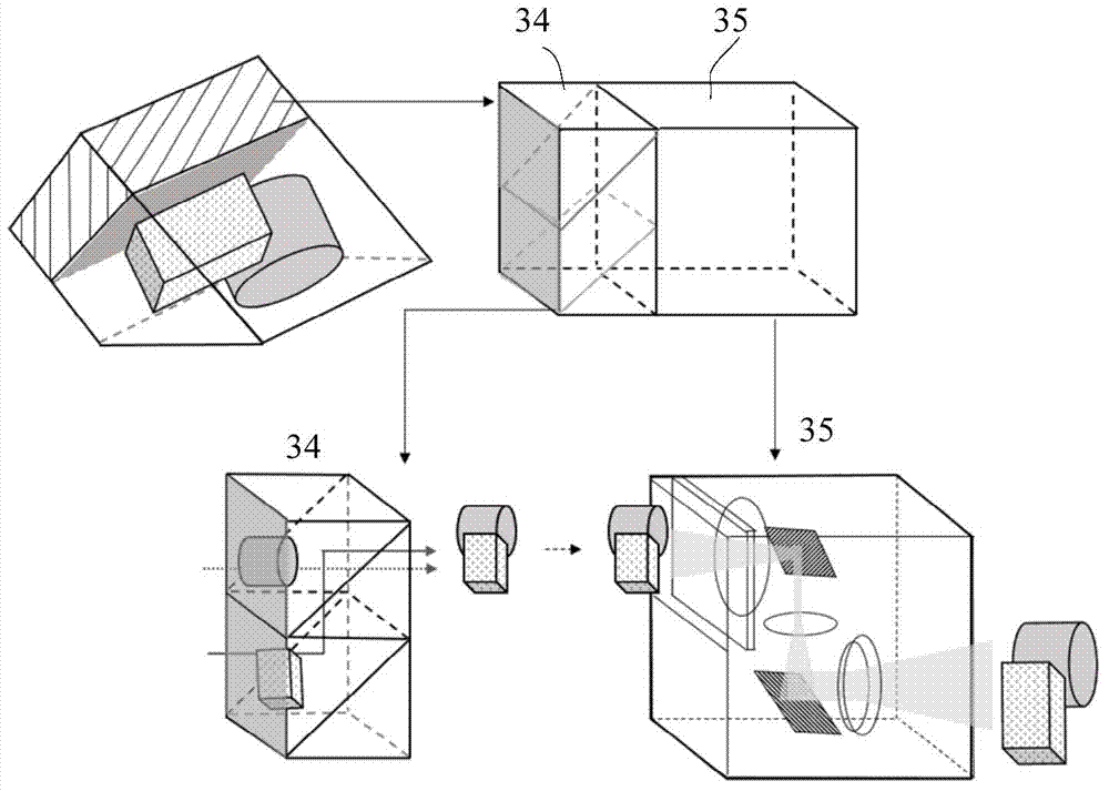
[0030] The microscopic system based on the in-situ stereo enhanced display of the embodiment of the first aspect of the present invention is as follows: figure 1 As shown, it includes a physical observation device 10 , a naked-eye three-dimensional display device 20 and an in-situ stereoscopic display device 30 .

[0031]The entity observation device 10 is aimed at the entity area, and is used for allowing the user to directly obtain entity visual images in real time. The so-called solid visual image refers to an image within th...


PUM


Abstract

The invention discloses a microscopic system and microscopic method based on in-situ three-dimensional enhanced display. By means of the microscopic system and microscopic method, a user can clearly and unceasingly observe an entity within a large view field range. The microscopic system comprises an entity observation device, a naked-eye three-dimensional display device and the in-situ three-dimensional display device. The entity observation device is aligned with an entity area and used for making the user directly obtain an entity visual image in real time. The naked-eye three-dimensional display device is used for providing a naked-eye true three-dimensional image related to the content of the entity visual image. The in-situ three-dimensional display device is connected with the entity observation device and the naked-eye three-dimensional display device and used for displaying the entity visual image and the naked-eye true three-dimensional image to the user after conducting in-situ three-dimensional perspective and fusion on the entity visual image and the naked-eye true three-dimensional image. The microscopic system has the advantages of being simple in structure, high in operation flexibility, capable of meeting different requirements, capable of achieving high-resolution three-dimensional fusion display or system portability and miniaturization, and the like.

Description

technical field [0001] The invention relates to microscopic technology, in particular to a microscopic system and a microscopic method based on in-situ stereo enhanced display. Background technique [0002] Microsystems are used more and more widely in research fields such as clinical medicine, biology, and pharmacy. Traditional microscopic displays are obtained directly through a microscope. Take Zeiss’ OPMI PENTERO 900 surgical microscope and Axio Imager 2 upright research microscope platform as an example. The observation system consists of the main objective lens, binocular lens tube and zoom unit. By matching eyepieces and objective lenses with different magnifications, different entities can be achieved. Magnification and working distance requirements. At the same time, the in-mirror projection function allows the user to fuse and display certain additional image information in the entity to guide the user's operation. However, the diameter of the field of view of t...

Claims


Application Information

Patent Timeline
IPC IPC(8): G02B27/22G02B21/36G03B35/18H04N13/04
CPCG02B21/36G02B30/34H04N13/111H04N13/139H04N13/305
Inventor 廖洪恩张欣然
Owner TSINGHUA UNIV
Learn More