
Indoor unit of air conditioner and air conditioner

An air-conditioning indoor unit and cavity technology, applied in air-conditioning systems, mechanical equipment, air humidification systems, etc., can solve the inconvenience of installation and use of air-conditioning indoor units, the lack of humidification function of air-conditioning indoor units, and the inability to meet the needs of indoor humidification, etc. Problems, to achieve the effect of improving utilization, avoiding splashing, and realizing circulating flow

Active Publication Date: 2015-01-14
HAIER GRP CORP +1
View PDF12 Cites 39 Cited by
  • Summary
  • Abstract
  • Description
  • Claims
  • Application Information

AI Technical Summary

Problems solved by technology

[0006] It can be seen from the above description that during the working process of the indoor unit of the air conditioner, the condensed water generated by the heat exchanger needs to be led out of the outdoor through a special pipe. Inconvenient installation and use of air conditioner indoor unit
[0007] In addition, the indoor environment is relatively dry, and the existing air-conditioning indoor units do not have a humidification function and cannot meet the needs of indoor humidification.

Method used


Image

  • Indoor unit of air conditioner and air conditioner
  • Indoor unit of air conditioner and air conditioner
  • Indoor unit of air conditioner and air conditioner

Examples


Embodiment Construction

[0038] In order to enable those skilled in the art to better understand the technical solutions of the present invention, the present invention will be further described in detail below in conjunction with the accompanying drawings and specific embodiments.

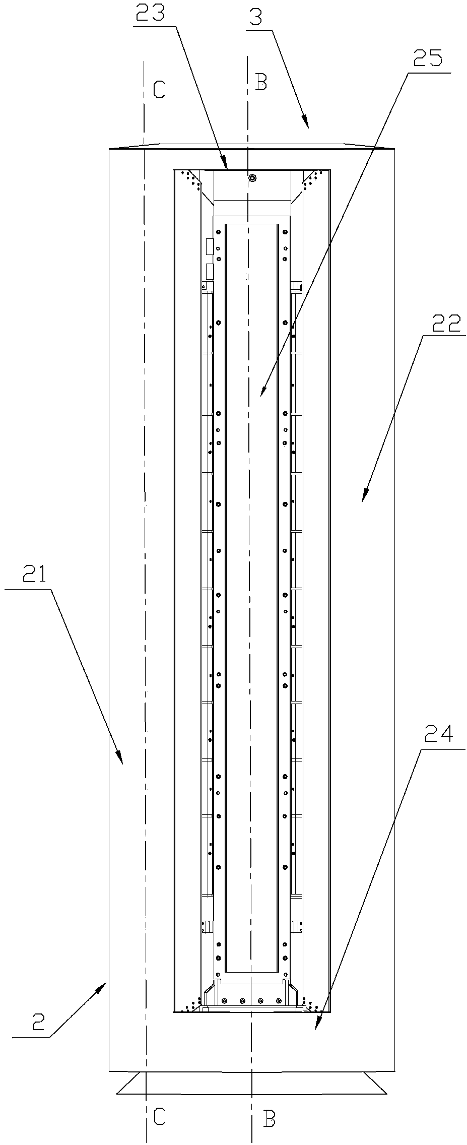
[0039] Please refer to image 3 and Figure 4 , image 3 It is a schematic diagram of the front structure of the air conditioner indoor unit provided by the present invention in a specific embodiment; Figure 4 for image 3 The cross-sectional structural schematic diagram of the air-conditioning indoor unit along the B-B direction in .

[0040] The air-conditioning indoor unit 3 of the present invention has a frame structure 2, and the frame structure 2 includes a left column 21, a right column 22, an upper frame 23 and a lower frame 24, and the left column 21 and the right column 22 are all arranged in a hollow cavity shape. Heat exchangers, cross-flow fans, air ducts and other components are arranged in the hollow c...


PUM


Abstract

The invention provides an indoor unit of an air conditioner and the air conditioner. The indoor unit of the air conditioner can collect condensate water. The indoor unit of the air conditioner is of a frame structure. A non-work cavity area is formed in the middle of the frame structure. A flow guiding plate which is inclined backwards is arranged in the cavity area. A water storage box and a water pump are arranged in the frame structure, wherein the water storage box is used for collecting the condensate water, and the water pump is used for conveying the condensate water in the water storage box to the top of the flow guiding plate. The bottom of the flow guiding plate is communicated with the water storage box. The water storage box collects the condensate water, and the condensate water is conveyed to the top of the flow guiding plate through the water pump. The condensate water flows downwards along the flow guiding plate under the action of gravity and diffuses to indoor air along with evaporation. Due to the fact that the flow guiding plate is backwards inclined, the condensate water flows downwards gradually at a certain inclination angle along the flow guiding plate, and splashing caused when water vertically flows is avoided. The bottom of the flow guiding plate is communicated with the water storage box, the condensate water flowing down from the flow guiding plate is recollected by the water storage box, and circulatory flow of the condensate water is achieved.

Description

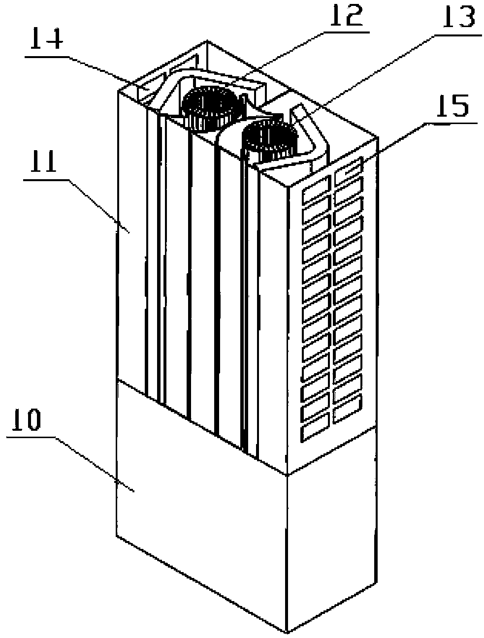
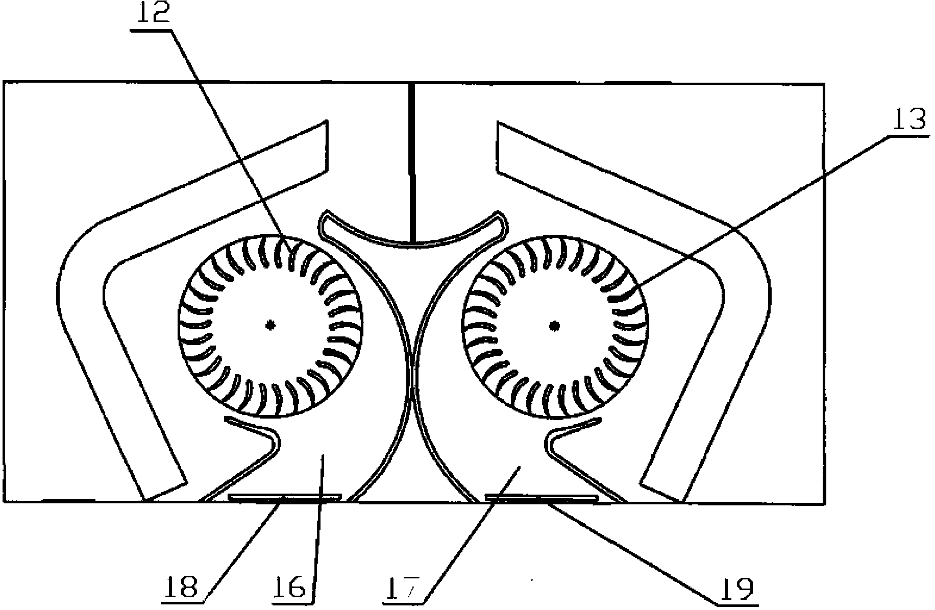
technical field [0001] The invention relates to the technical field of air conditioners, in particular to an air conditioner indoor unit. The present invention also relates to an air conditioner provided with the above air conditioner indoor unit. Background technique [0002] The air conditioner indoor unit is a heat exchanger installed indoors, and is an important part of the current split air conditioner. Usually, the existing air conditioner indoor unit has a vertical structure, and the whole body of the air conditioner is arranged vertically, which is also called a floor-standing air conditioner indoor unit. [0003] Please refer to figure 1 and figure 2 , figure 1 It is a three-dimensional structural schematic diagram of a setting method of an air-conditioning indoor unit in the prior art; figure 2 for figure 1 The schematic diagram of the cross-sectional structure of the indoor unit of the air conditioner shown. [0004] The patent No. CN101957020A discloses ...

Claims


Application Information

Patent Timeline
IPC IPC(8): F24F1/00F24F13/22F24F6/02F24F11/02
CPCF24F1/00F24F3/14F24F8/10F24F8/108F24F8/158F24F8/167F24F8/192F24F8/30F24F8/50
Inventor 周枢吴剑费兆军杜鹃
Owner HAIER GRP CORP
Learn More