


Quick Research
Generate reliable direction feasibility study reports for your R&D in just a few steps.

Technical Q&A
Discover and master advanced knowledge NOW. Basics, ideas, possibilities, all at once.

Find Solutions
As an expert in R&D theories, this can generate solutions to your technical problems instantly.

Evaluate Feasibility
Analyze your overall solution with one click, know your potential R&D risks in advance.

Monitor Landscape
Get weekly tech updates, stay abreast of the latest tech innovations and key insights.
Vehicle and vehicle cruise control method
A cruise control and vehicle technology, applied in the field of vehicle and vehicle cruise control, can solve the problems of complex power transmission system structure, complex control strategy, low transmission efficiency, etc., achieve the best fuel economy, reduce fuel consumption, and increase the number of operating modes Effect
- Summary
- Abstract
- Description
- Claims
- Application Information
AI Technical Summary
Problems solved by technology
Method used
Image

Examples
Embodiment 1
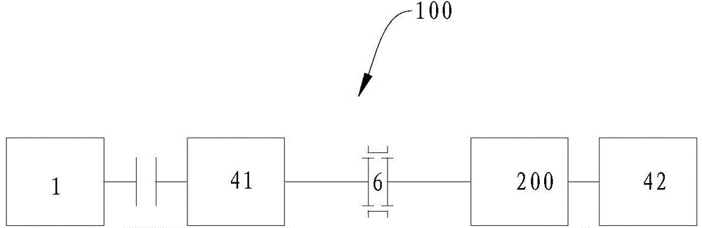
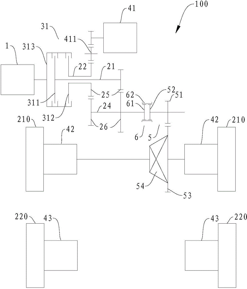
[0156] Such as figure 2 As shown, the engine unit 1 is connected to the input end 313 of the double clutch 31, the first output end 311 of the double clutch 31 is connected to the first input shaft 21, and the second output end 312 of the double clutch 31 is connected to the second input shaft 22, The second input shaft 22 is coaxially sleeved on the first input shaft 21 .
[0157] A driving gear 25 is fixedly arranged on the first input shaft 21 and the second input shaft 22 respectively, and the first motor generator 41 is indirectly driven with the driving gear 25 on the second input shaft 22 through an intermediate gear 411 . Two driven gears 26 are fixedly arranged on the output shaft 24 , and the two driven gears 26 respectively mesh with the driving gears 25 on the first input shaft 21 and the second input shaft 22 to form two transmission gears.
[0158] The synchronizer 6 is arranged on the output shaft 24, and the driving gear of the main reducer (that is, the outp...
Embodiment 2
[0186] Such as image 3 As shown, the power transmission system 100 in this embodiment and figure 2 The difference of the power transmission system 100 in the above may only lie in the arrangement form of the second motor generator 43 . In this embodiment, each second motor-generator 43 drives the corresponding rear wheel 220 through a second speed change mechanism 72, and the remaining parts can be connected with figure 2 The power transmission system 100 in the embodiment is basically the same, and will not be repeated here. As for the specific working conditions, it is related to figure 2 The power transmission system 100 in the embodiment is basically the same, and the only difference is that the power transmission between the second motor generator 43 and the corresponding rear wheel 220 needs to go through the second transmission mechanism 72 , which will not be described in detail here.
Embodiment 3
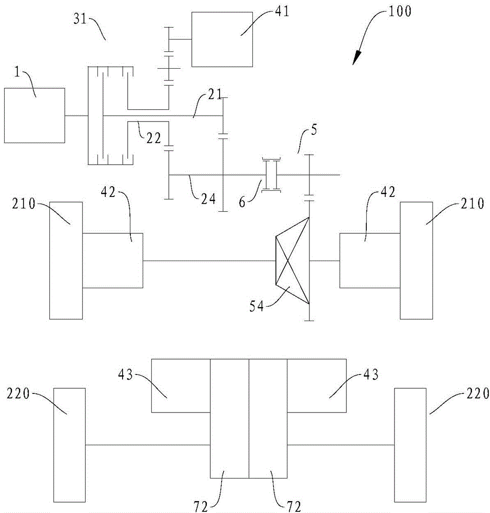
[0188] Such as Figure 4 As shown, the power transmission system 100 in this embodiment and figure 2 The difference of the power transmission system 100 in the above may only lie in the arrangement form of the second motor generator 43 . In this embodiment, the second motor-generator 43 is one and drives the corresponding rear wheel 220 through a first speed change mechanism 71, and the remaining parts can be connected with figure 2 The power transmission system 100 in the embodiment is basically the same, and will not be repeated here. As for the specific working conditions, it is related to figure 2 The power transmission system 100 in the embodiment is basically the same, and the only difference is that the two rear wheels 220 are driven by a second motor-generator 43 and a first speed change mechanism 71, so without adding new components, only The differential function of the two rear wheels 220 cannot be realized by a motor and a transmission mechanism, but it can b...
PUM
 Abstract
Description
Claims
Application Information
 - R&D Engineer
- R&D Manager
- IP Professional
- Industry Leading Data Capabilities
- Powerful AI technology
- Patent DNA Extraction
Browse by: Latest US Patents, China's latest patents, Technical Efficacy Thesaurus, Application Domain, Technology Topic, Popular Technical Reports.
© 2024 PatSnap. All rights reserved.Legal|Privacy policy|Modern Slavery Act Transparency Statement|Sitemap|About US| Contact US: help@patsnap.com