


Quick Research
Generate reliable direction feasibility study reports for your R&D in just a few steps.

Technical Q&A
Discover and master advanced knowledge NOW. Basics, ideas, possibilities, all at once.

Find Solutions
As an expert in R&D theories, this can generate solutions to your technical problems instantly.

Evaluate Feasibility
Analyze your overall solution with one click, know your potential R&D risks in advance.

Monitor Landscape
Get weekly tech updates, stay abreast of the latest tech innovations and key insights.
Dehumidifying apparatus, dehumidifying method and wind-energy current transformer of dehumidifying apparatus
A converter and wind energy technology, applied in the field of dehumidification, can solve problems such as device condensation, electronic device short circuit, damage, etc., to achieve the effect of accelerating air flow, improving reliability, and simple control
- Summary
- Abstract
- Description
- Claims
- Application Information
AI Technical Summary
Problems solved by technology
Method used
Image

Examples
Embodiment 1
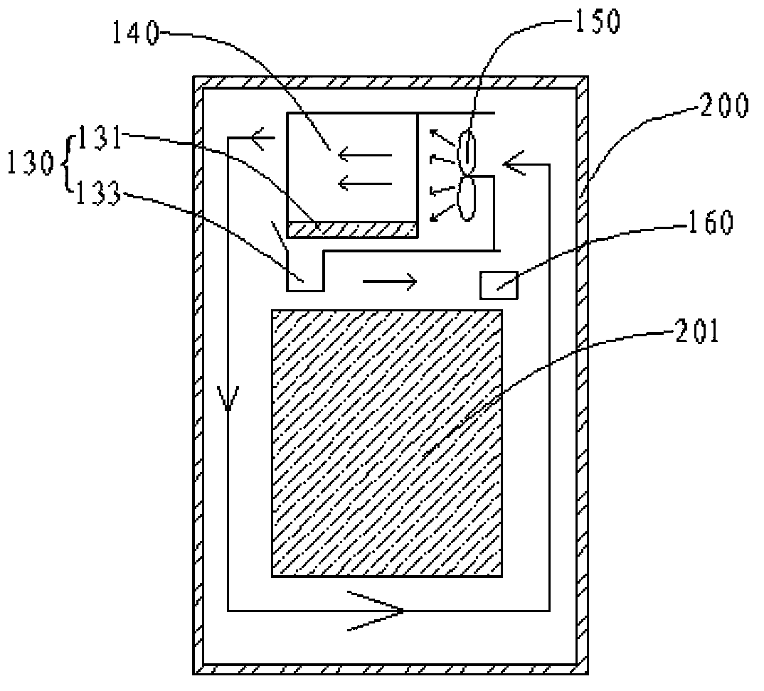
[0075] Such as figure 1 with figure 2 Shown is a schematic diagram of a wind energy converter in the first preferred embodiment and a control schematic diagram of the dehumidification device 100 of the wind energy converter.
[0076] The cabinet body of the wind energy converter includes a cabinet body 200 , an electronic device 201 and a dehumidification device 100 arranged in the cabinet body 200 .
[0077] The dehumidification device 100 is installed on the top of a cabinet 200 of a wind energy converter.
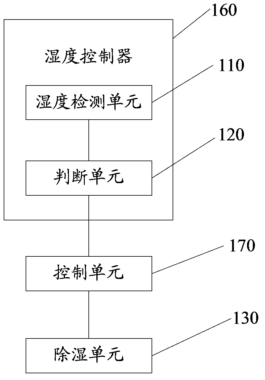
[0078] The dehumidification device 100 includes a humidity controller 160 , a control unit 170 and a dehumidification unit 130 . The humidity controller 160 includes a humidity detection unit 110 and a judging unit 120 for detecting that the current humidity of the cabinet body 200 is a first humidity value.
[0079] The judgment unit 120 is connected to the humidity detection unit 110 and compares the first humidity value detected by the humidity detection unit 110 ...
Embodiment 2
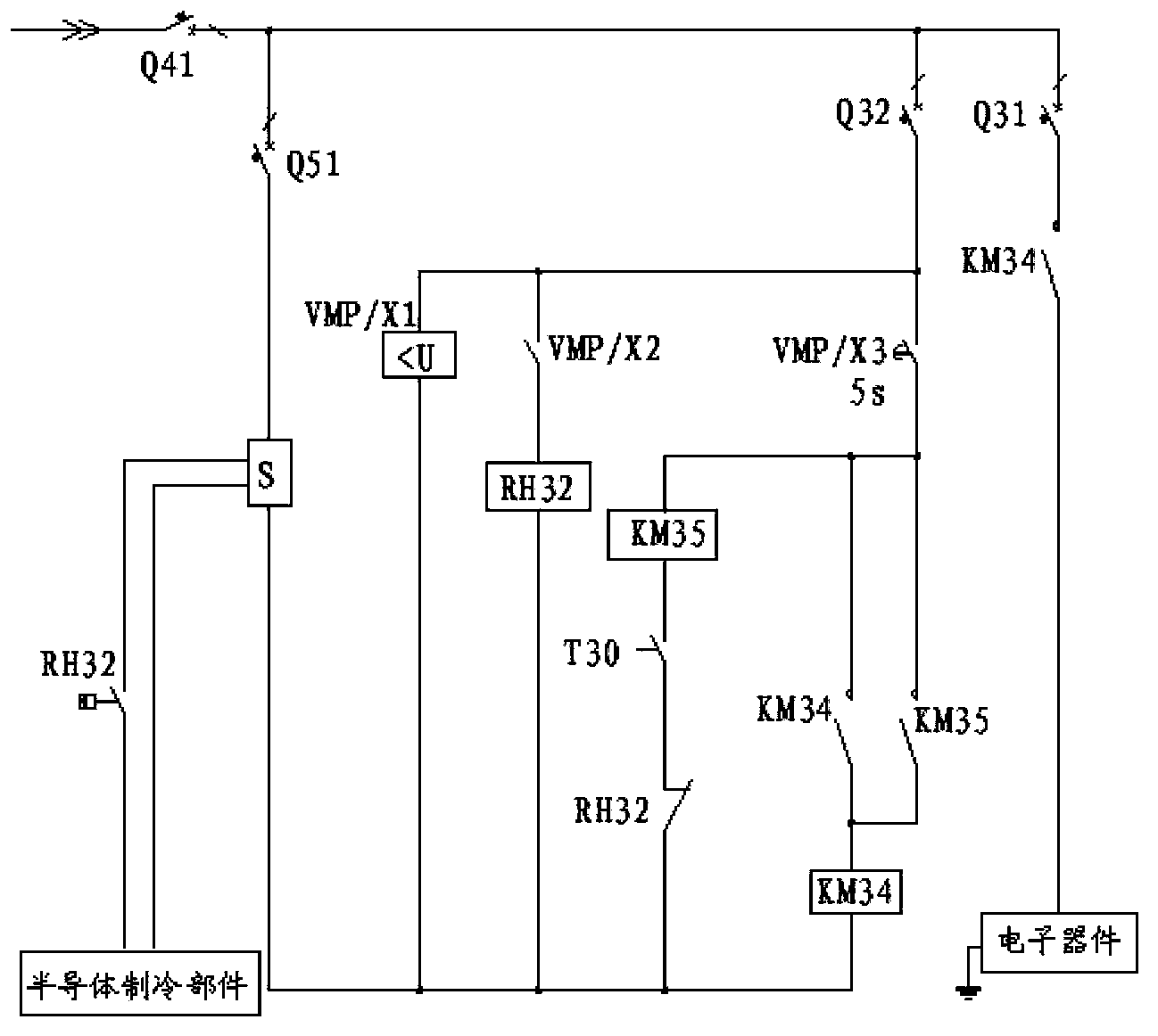
[0097] Such as Figure 4 Shown is a circuit control diagram of a dehumidification device. The circuit control principle of the wind energy converter is the same as the circuit control principle in the embodiment, the difference is that, for the humidity controllers of the two cabinets at the same time, each cabinet is provided with a dehumidification device, which includes two humidity detection Units RH32 and RH33 and two sets of peltier cooling components. In other embodiments, the air in three or more cabinets can be dehumidified at the same time, and the number of semiconductor refrigeration components in each cabinet is not limited, and can be set according to needs.
Embodiment 3
[0099] Such as Figure 5 As shown, it is a schematic diagram of a wind energy converter 300 according to the third preferred embodiment. The wind energy converter 300 includes a cabinet body 310 , an electronic device 311 and a dehumidification device 320 arranged in the cabinet body 310 .
[0100] The dehumidification device 320 includes a humidity detection unit, a judgment unit, a dehumidification unit 323 , a heat exchange unit 324 and two airflow acceleration units 325 .
[0101] In this embodiment, the dehumidification principle of the dehumidification device 320 is the same as that of the dehumidification device 100 in Embodiment 1, and for the sake of brief description, details are not repeated here. The difference is that the positional relationship of the dehumidification unit 323, the heat exchange unit 324 and the two airflow acceleration units 325 of the dehumidification device 320 in the cabinet body 310 is the same as that of the dehumidification unit 130, the ...
PUM
 Abstract
Description
Claims
Application Information
 - R&D Engineer
- R&D Manager
- IP Professional
- Industry Leading Data Capabilities
- Powerful AI technology
- Patent DNA Extraction
Browse by: Latest US Patents, China's latest patents, Technical Efficacy Thesaurus, Application Domain, Technology Topic, Popular Technical Reports.
© 2024 PatSnap. All rights reserved.Legal|Privacy policy|Modern Slavery Act Transparency Statement|Sitemap|About US| Contact US: help@patsnap.com