


Quick Research
Generate reliable direction feasibility study reports for your R&D in just a few steps.

Technical Q&A
Discover and master advanced knowledge NOW. Basics, ideas, possibilities, all at once.

Find Solutions
As an expert in R&D theories, this can generate solutions to your technical problems instantly.

Evaluate Feasibility
Analyze your overall solution with one click, know your potential R&D risks in advance.

Monitor Landscape
Get weekly tech updates, stay abreast of the latest tech innovations and key insights.
Photovoltaic inverter control method and system
A photovoltaic inverter and control method technology, which is applied in photovoltaic modules, photovoltaic power generation, and irreversible DC power input conversion into AC power output, etc. efficiency and other issues to achieve the effect of reducing self-loss, increasing power generation, and improving work efficiency
- Summary
- Abstract
- Description
- Claims
- Application Information
AI Technical Summary
Problems solved by technology
Method used
Image

Examples
Embodiment 1
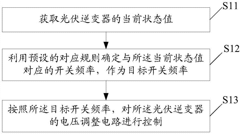
[0044] refer to figure 2 The shown flow chart of an embodiment of a control method for a photovoltaic inverter of the present invention is applied to a photovoltaic power generation system, and the method may include the following steps:
[0045] Step S11: Obtain the current state value of the photovoltaic inverter.
[0046] In this embodiment, the current state value may specifically be: the input current of the voltage regulation circuit of the photovoltaic inverter, the input current and input voltage of the voltage regulation circuit of the photovoltaic inverter, the inverter circuit of the photovoltaic inverter The input current of the photovoltaic inverter, the input voltage of the inverter circuit of the photovoltaic inverter, or the current power of the photovoltaic inverter, etc., are not specifically limited in the present invention.
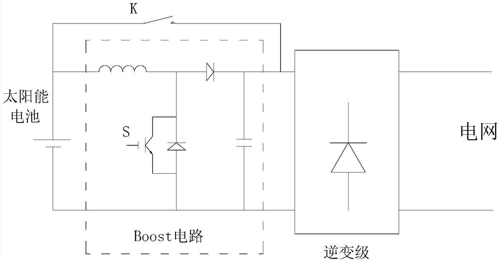
[0047] Wherein, the voltage adjustment circuit can be a Boost circuit, a double Boost circuit, a buck-boost circuit, etc., a circui...
Embodiment 2
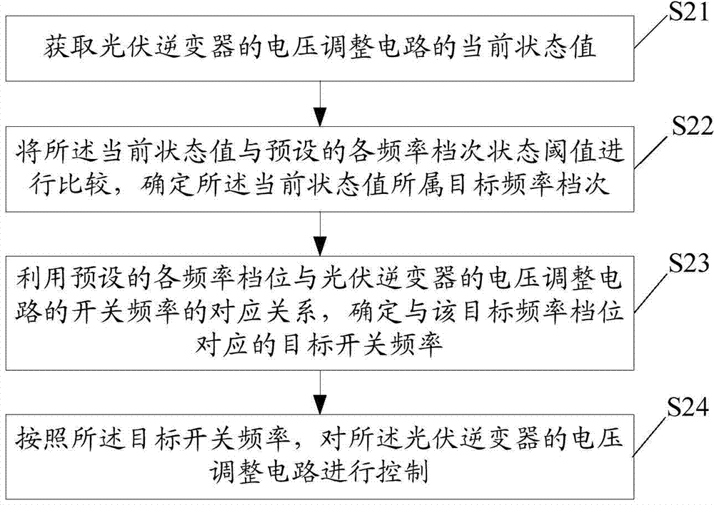
[0061] refer to image 3 Shown is a schematic flowchart of a specific embodiment of another photovoltaic inverter control method of the present invention, the method may specifically include the following steps:
[0062] Step S21: Obtain the current state value of the voltage regulation circuit of the photovoltaic inverter.
[0063] Step S22: comparing the current state value with the preset state thresholds of each frequency grade, and determining the target frequency grade to which the current state value belongs;
[0064] Specifically, this embodiment may judge whether the current state value is greater than the preset state threshold of the frequency class according to the order of the state thresholds of the preset frequency classes from small to large, and if so, use the currently judged frequency class as the target Frequency level, if not, continue to judge whether the current state value is greater than the state threshold of the next frequency level, until the targe...
Embodiment 3
[0072] refer to Figure 4 Shown is a schematic structural diagram of a control system embodiment of a photovoltaic inverter of the present invention, the system may include:
[0073] The obtaining module 31 is used to obtain the current state value of the photovoltaic inverter.
[0074] In this embodiment, the current state value obtained by the obtaining module 31 may be the input current of the voltage regulation circuit of the photovoltaic inverter, or the input current and input voltage of the voltage regulation circuit of the photovoltaic inverter, or the The input current of the inverter circuit of the photovoltaic inverter, or the input voltage of the inverter circuit of the photovoltaic inverter, or the current power of the photovoltaic inverter.
[0075] A determining module 32, configured to determine a switching frequency corresponding to the current state value by using a preset rule as a target switching frequency;
[0076] Optionally, the determination module 3...
PUM
 Abstract
Description
Claims
Application Information
 - R&D Engineer
- R&D Manager
- IP Professional
- Industry Leading Data Capabilities
- Powerful AI technology
- Patent DNA Extraction
Browse by: Latest US Patents, China's latest patents, Technical Efficacy Thesaurus, Application Domain, Technology Topic, Popular Technical Reports.
© 2024 PatSnap. All rights reserved.Legal|Privacy policy|Modern Slavery Act Transparency Statement|Sitemap|About US| Contact US: help@patsnap.com