
Diffuse reflection laser ranging and high resolution imaging synchronous measurement photoelectric telescope system

A technology of photoelectric telescope and laser ranging, applied in the field of photoelectric telescope

Active Publication Date: 2015-01-07
YUNNAN ASTRONOMICAL OBSERVATORY CHINESE ACAD OF SCI
View PDF5 Cites 25 Cited by
  • Summary
  • Abstract
  • Description
  • Claims
  • Application Information

AI Technical Summary

Problems solved by technology

Page 943 of SPIE published in 2004 introduced that the 1.2m adaptive optics telescope of Yunnan Astronomical Observatory can be used for high-resolution imaging of targets, but this adaptive optics telescope is only used for high-resolution imaging and cannot be used for diffuse reflection (formerly a satellite )Laser Ranging

Method used


Image

  • Diffuse reflection laser ranging and high resolution imaging synchronous measurement photoelectric telescope system
  • Diffuse reflection laser ranging and high resolution imaging synchronous measurement photoelectric telescope system
  • Diffuse reflection laser ranging and high resolution imaging synchronous measurement photoelectric telescope system

Examples


Embodiment Construction

[0039] The present invention will be described in further detail below in conjunction with the accompanying drawings.

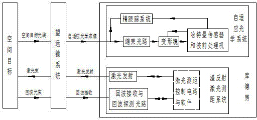
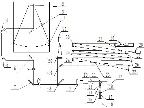
[0040] like figure 1 As shown, a photoelectric telescope system for simultaneous measurement of diffuse reflection laser ranging and high-resolution imaging, including laser emission, echo reception and adaptive optics imaging, is as follows:

[0041] Laser emission: The laser ranging control circuit and software send out a laser emission signal, and the laser in the Kud room enters the telescope through the laser emission path, and then emits to the space target through the telescope;

[0042] Echo reception: The echo beam from the space target is received by the telescope, and then enters the echo reception and echo detection optical path of the Kud room, and the echo signal is generated and sent to the laser ranging control circuit and software, and diffuse reflection is obtained after processing The distance value of laser ranging;

[0043] Adaptive op...


PUM


Abstract

The invention relates to a diffuse reflection laser ranging and high-resolution imaging synchronous measurement photoelectric telescope system capable of being used for space debris and belongs to the technical field of photoelectric telescopes. The system comprises a laser emitting part, an echo receiving part and a self-adaptive optical imaging part. According to the laser emitting part, laser light emitted by a laser enters a telescope through a laser emitting light path to be emitted to a space target. According to the echo receiving part, an echo light beam is received by the telescope and then enters an echo receiving and detecting light path, echo signals are generated and then transmitted to a laser ranging control circuit, and a laser ranging distance value is obtained after software processing. According to the self-adaptive optical imaging part, the space target light is received by the telescope, enters a self-adaptive optical system and is shrunk by a beam shrinking light path, a Hartmann sensor and a wavefront detector are used for detecting overall wavefront inclination and wavefront errors to obtain the overall wavefront inclination degree and wavefront error data which are used for controlling a fine tracking system to correct the wavefront inclination and controlling a deformable mirror to correct the wavefront errors, and therefore a high-resolution image is obtained.

Description

technical field [0001] The invention belongs to the technical field of photoelectric telescopes, and relates to a photoelectric telescope system and a photoelectric telescope, in particular, it can be used for simultaneous measurement of space debris diffuse reflection laser ranging and high-resolution imaging. Background technique [0002] Satellite Laser Ranging (SLR) is a technology initiated by NASA in the early 1960s to use space technology to study geodynamics, geodesy, geophysics and astronomy, etc. means. It uses the measurement of the round-trip flight time of laser pulses between the observation station and the satellite, thereby calculating the distance from the satellite to the station. It is currently the most accurate technical method in space target distance measurement. Since the laser is monochromatic and has good directionality, the laser ranging can simultaneously provide the target's azimuth, height and distance information. Conventional laser ranging r...

Claims


Application Information

Patent Timeline
IPC IPC(8): G01S17/08G02B27/00G02B26/06G01J9/00
CPCG01S17/08G02B27/0068
Inventor 李语强伏红林李祝莲李荣旺常翔周钰翟东升熊耀恒
Owner YUNNAN ASTRONOMICAL OBSERVATORY CHINESE ACAD OF SCI
Learn More