
Accurate positioning method for automobile

A precise positioning and automotive technology, applied in the automotive field, can solve the problems of waste of information resources, poor quality of alarm sound, false alarms, etc., and achieve the effects of accurate obstacle distance, reduction of detection blind spots, and reduction of temperature errors.

Inactive Publication Date: 2015-01-07
SAIC MOTOR
View PDF4 Cites 5 Cited by
  • Summary
  • Abstract
  • Description
  • Claims
  • Application Information

AI Technical Summary

Problems solved by technology

[0004] However, the propagation speed of ultrasonic waves in the air is easily affected by temperature. The traditional reversing radar system does not perform temperature correction. Report the situation
[0005] In addition, the traditional reversing radar system only has sound prompts, which will lead to the inability to recognize different frequency sound alarms in a noisy environment, and lacks the flashing reminder of the reversing warning lights
Only the controller calculates the distance between the obstacle and the rear of the vehicle, which cannot be displayed on the screen, and the distance of the obstacle cannot be intuitively understood. The obstacle distance data cannot be shared with other modules of the vehicle body, resulting in a waste of information resources
[0006] With the development of vehicle bus technology, more and more vehicles are equipped with CAN bus. The quality of the alarm sound of the traditional reversing radar system is rough, and it is impossible to call the car audio through the vehicle CAN bus to improve the quality of the alarm sound.

Method used


Image

  • Accurate positioning method for automobile
  • Accurate positioning method for automobile

Examples


Embodiment 1

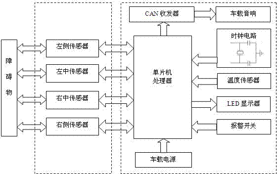
[0022] like figure 1 As shown in the figure, a method for precise positioning of automobiles, firstly, an ultrasonic sensor and a temperature sensor are installed on the vehicle. For the arrangement of the acoustic wave sensor, considering the possible collision position of the vehicle when reversing, a total of four are set in the present invention, and the four described The acoustic wave sensors are evenly distributed laterally on the rear bumper, and are located at the left, middle left, middle right, and right positions of the rear bumper; for the arrangement of the temperature sensor, in the present invention, in order to avoid the temperature sensor being affected by the vehicle startup state The influence of its own heat dissipation improves the accuracy of ambient temperature measurement. The temperature sensor is installed on the rear bumper of the vehicle, located in the middle of the rear bumper, between the two sensors in the middle. In this embodiment, The tem...


PUM


Abstract

The invention relates to the field of automobiles, in particular to an accurate positioning method for an automobile. The accurate positioning method for the automobile includes the steps that a standard barometric pressure value and a common temperature range are selected; then all values corresponding to temperature and ultrasonic velocity are obtained within the common temperature range through an experiment under the standard barometric pressure value; then the temperature and the ultrasonic velocity are fitted to obtain a temperature and speed function relation; finally, signals of ultrasonic sensors and a temperature sensor are transmitted to a vehicle-mounted controller, the vehicle-mounted controller works out current ultrasonic velocity through the temperature and velocity function relation according to the signal of the temperature sensor, and then the signals of the ultrasonic sensors are combined with the current ultrasonic velocity to obtain the distance between the installation position points of the ultrasonic sensors and the position of an obstacle. The distance from the obstacle can be detected more accurately through the ultrasonic sensors, alarm sound can have more features, a better function can be achieved, the distance from the obstacle can be directly displayed on a displayer inside a vehicle, and therefore a driver learns about the position of the obstacle more visually.

Description

technical field [0001] The invention relates to the field of automobiles, in particular to a method for positioning an automobile. Background technique [0002] With the increase of car ownership, reversing in space-constrained places often makes ordinary drivers at a loss, especially when novice reversing, they may scratch with other vehicles or even knock down pedestrians. Although vehicles are equipped with rear-view mirrors, there will inevitably be blind spots, which will undoubtedly increase the probability of reversing accidents. [0003] The reversing radar system is a safety auxiliary device when the car is reversing. Its working principle is to install an ultrasonic sensor on the rear bumper of the vehicle to detect the obstacles behind the car when reversing and help the driver "see" the obstacles in the blind spot behind the car. , and calculate the distance between the rear bumper and the obstacle. The use of different frequencies of sounds to issue alarm sign...

Claims


Application Information

Patent Timeline
Patent Type & Authority Applications(China)
IPC IPC(8): G01S15/08G01S15/93G01S7/52H04L12/40G05B19/05
CPCG01S15/931G01S7/52006G01S15/08G01S2015/937
Inventor 石存杰张静雅朱卫贤卢絮程智
Owner SAIC MOTOR
Learn More