
Water turbine with water pumping function

A water turbine and functional technology, applied in the direction of pumps, pump devices, mechanical equipment, etc., can solve the problems of high production cost, high cost, dependence, etc., and achieve the effect of good sealing performance and small energy loss

Active Publication Date: 2015-01-07
郑广生
View PDF6 Cites 7 Cited by
  • Summary
  • Abstract
  • Description
  • Claims
  • Application Information

AI Technical Summary

Problems solved by technology

[0002] Modern water turbine technology often relies on the construction of dams to increase the potential energy of water so that water energy resources can be effectively utilized; however, the existing water turbine technology that does not require dams to convert water kinetic energy into mechanical energy has the bottleneck of low efficiency and high cost
The amount of water energy resources in rivers and oceans is extremely huge, but due to limited conditions, most places are not suitable for building dams, so that this part of water energy resources cannot be used under the premise of existing hydraulic turbine technology. what we use
[0003] On the other hand, water pumps are important equipment for agricultural irrigation and breeding. Generally, they are mainly driven by electricity or gasoline or diesel engines. However, due to their high production costs and heavy dependence on modern industrial products, they are not easy to apply to remote places.
In order to overcome the above problems, there has been a water wheel pump using natural energy consisting of an axial flow turbine and a centrifugal water pump in the prior art, but it needs to build water wheel pumping stations on rivers and channels with a drop greater than 1 meter. There are restrictions such as high cost, low efficiency, and inability to move the dam

Method used


Image

  • Water turbine with water pumping function
  • Water turbine with water pumping function
  • Water turbine with water pumping function

Examples


Embodiment 1

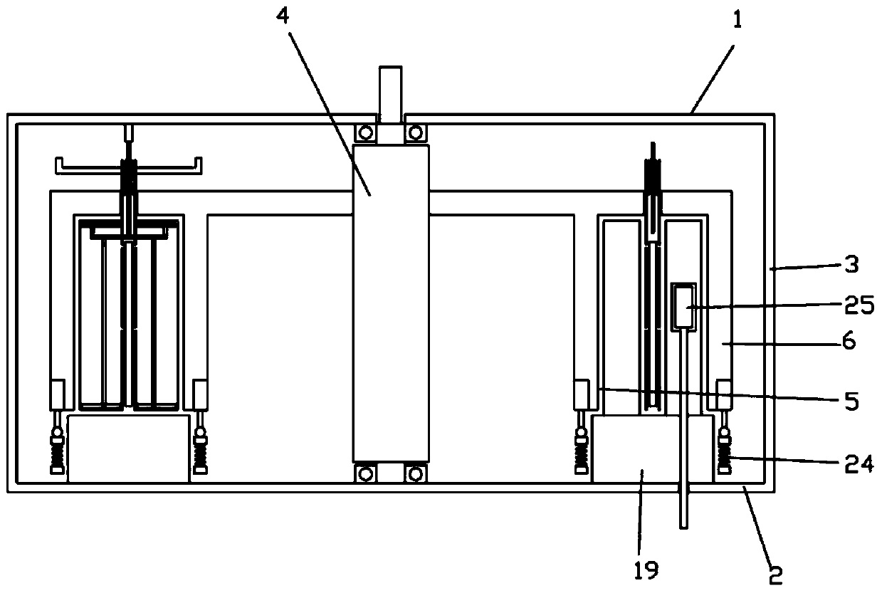
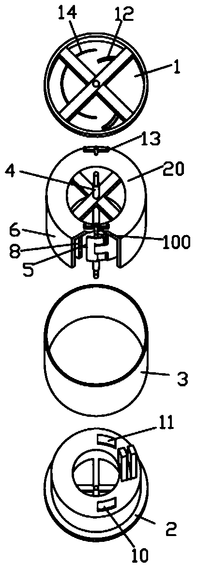
[0042] Such as Figure 1-Figure 7 As shown, a water turbine with the function of pumping water includes a shell composed of an upper end cover 1, a lower end cover 2 and a side wall 3, and a rotatable water wheel shaft 4 is installed between the upper end cover 1 and the lower end cover 2. A rotor is installed on the water wheel shaft 4, and the lower end cover 2 is provided with a water inlet 10 and a water outlet 11 in the opposite direction centered on the water wheel shaft 4.

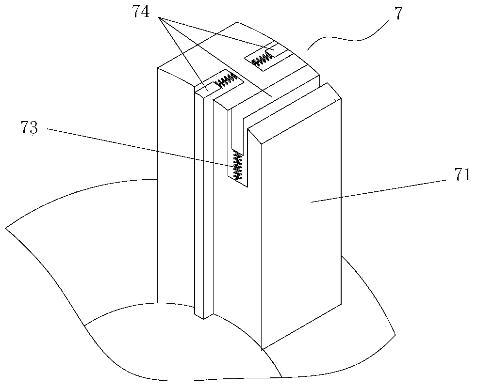
[0043]The rotor is sequentially provided with an outer cylinder 6, a blade cylinder 8 and an inner cylinder 5 coaxial with each other from the outside to the inside, an outer ring is formed between the outer cylinder 6 and the blade cylinder 8, and the blade cylinder 8 An inner ring is formed between the inner cylinder and the inner cylinder 5. The axial cross-sectional areas of the outer ring and the inner ring are not equal. The side communicates with the water outlet 11; the outer cylinder 6, th...

Embodiment 2

[0055] see Figure 7-Figure 9 The difference between this embodiment and Embodiment 1 of the hydraulic turbine with pumping function shown is that there is no outer cylinder on the rotor of the hydraulic turbine with pumping function described in this example, but the outer cylinder is replaced by side wall 3 function.

[0056] Specifically, see Figure 8-Figure 9 , the water turbine with the function of pumping water described in this embodiment includes a housing composed of an upper end cover 1, a lower end cover 2 and a side wall 3, and a rotatable water pump is installed between the upper end cover 1 and the lower end cover 2. The wheel shaft 4, the rotor is installed on the water wheel shaft 4, the side wall 3 is provided with a water inlet 10' and a water outlet 11' in the opposite direction centered on the water wheel shaft 4, and the rotors are arranged in sequence from outside to inside There are mutually coaxial blade cylinders 8 and inner cylinders 5, an outer ri...

Embodiment 3

[0063] see Figure 11 , this embodiment shows the application of the coaxial connection of the hydraulic turbine with pumping function in embodiment 1 or embodiment 2. The hydraulic turbine with pumping function of the present invention works as a water pump with the The direction of rotation is reversed. In this embodiment, the upper water turbine that also has the function of pumping water is used as a water turbine for output power, and the lower water turbine is used as a water pump. When the device is placed in the water flow, the power output from the upper water turbine is transmitted to the lower water pump through the water wheel shaft 4 to drive the rotor to rotate, thereby completing the function of pumping water. Can make the scope of application wider.


PUM


Abstract

The invention provides a water turbine with a water pumping function. The water turbine comprises a shell consisting of an upper end cover, a lower end cover and a side wall, wherein a rotatable water-wheel shaft is mounted between the upper end cover and the lower end cover; a rotor is mounted on the water-wheel shaft; a water inlet and a water outlet are formed in the shell; the rotor comprises ring grooves formed by adjacent coaxial cylinders; a water stop device used for closing the ring grooves is arranged on the shell; blade openings are formed in a blade cylinder between the adjacent ring grooves in the symmetric direction; rotatable blades are fixed to the blade openings through a blade shaft; a blade open-close guide rail is arranged on the upper end cover; and a blade control rod is arranged at the top of the blade shaft, is movably inserted into the blade open-close guide rail and drives the blade shaft to rotate when the rotor rotates. The water turbine with the water pumping function can utilize the water flow energy of rivers, streams and other running waters, as well as the water flow kinetic energy of ocean tides, and can also utilize water flow energy conversion in the natural state to achieve the water pumping purpose.

Description

technical field [0001] The invention relates to the field of water energy utilization, more specifically, to a water turbine with the function of pumping water. Background technique [0002] Modern water turbine technology often relies on the construction of dams to increase the potential energy of water so that water energy resources can be effectively utilized; however, the existing water turbine technology that does not require dams to convert water kinetic energy into mechanical energy has the bottleneck of low efficiency and high cost . The amount of water energy resources in rivers and oceans is extremely huge, but due to limited conditions, most places are not suitable for building dams, so that this part of water energy resources cannot be used under the premise of existing hydraulic turbine technology. We use. [0003] On the other hand, water pumps are important equipment for agricultural irrigation and breeding. Generally, they are mainly driven by electricity o...

Claims


Application Information

Patent Timeline
IPC IPC(8): F03B3/00F03B3/12F03B11/02F03B13/26F04D1/00F04D13/04
CPCF03B3/00F03B3/121F03B11/02F03B13/26F04D13/04F03B3/12F04D1/00Y02E10/20Y02E10/30
Inventor 郑广生
Owner 郑广生
Learn More