
Guide rail clamping fixing device

A guide rail and buckle technology, which is applied in the direction of positioning device, workpiece clamping device, clamping, etc., can solve the problems of affecting work efficiency, limited moving direction, inconvenient disassembly and assembly, and achieves the effect of conveniently locking the body and improving efficiency

Active Publication Date: 2015-01-07
OMRON SHANGHAI
View PDF7 Cites 1 Cited by
  • Summary
  • Abstract
  • Description
  • Claims
  • Application Information

AI Technical Summary

Problems solved by technology

In the existing structure, insufficient consideration is given to the convenience of disassembly and assembly of these fixtures (such as controllers), resulting in very inconvenient disassembly and assembly, which greatly affects work efficiency
Specifically, the rails in this structure are usually close to immovable objects, such as walls, cabinet walls, etc., and in the fields of electrical, communication and numerical control, there is usually an electrical connection between fixed objects (such as controllers). Sexual connection, its movement direction is limited, it is only convenient to extract in the axial direction
However, in the prior art, it is necessary to rotate the fixture (such as a controller) in the vertical plane or use a tool near the guide rail to loosen the clamping device of the guide rail during disassembly, which is very inconvenient to operate, especially in a large number of fixtures ( Such as the batch operation of the controller), which seriously affects the work efficiency

Method used


Image

  • Guide rail clamping fixing device
  • Guide rail clamping fixing device
  • Guide rail clamping fixing device

Examples


Embodiment Construction

[0034] Typical embodiments embodying the features and advantages of the present invention will be described in detail in the following description. It should be understood that the present invention is capable of various changes in different embodiments without departing from the scope of the present invention, and that the description and drawings therein are illustrative in nature and not limiting. this invention.

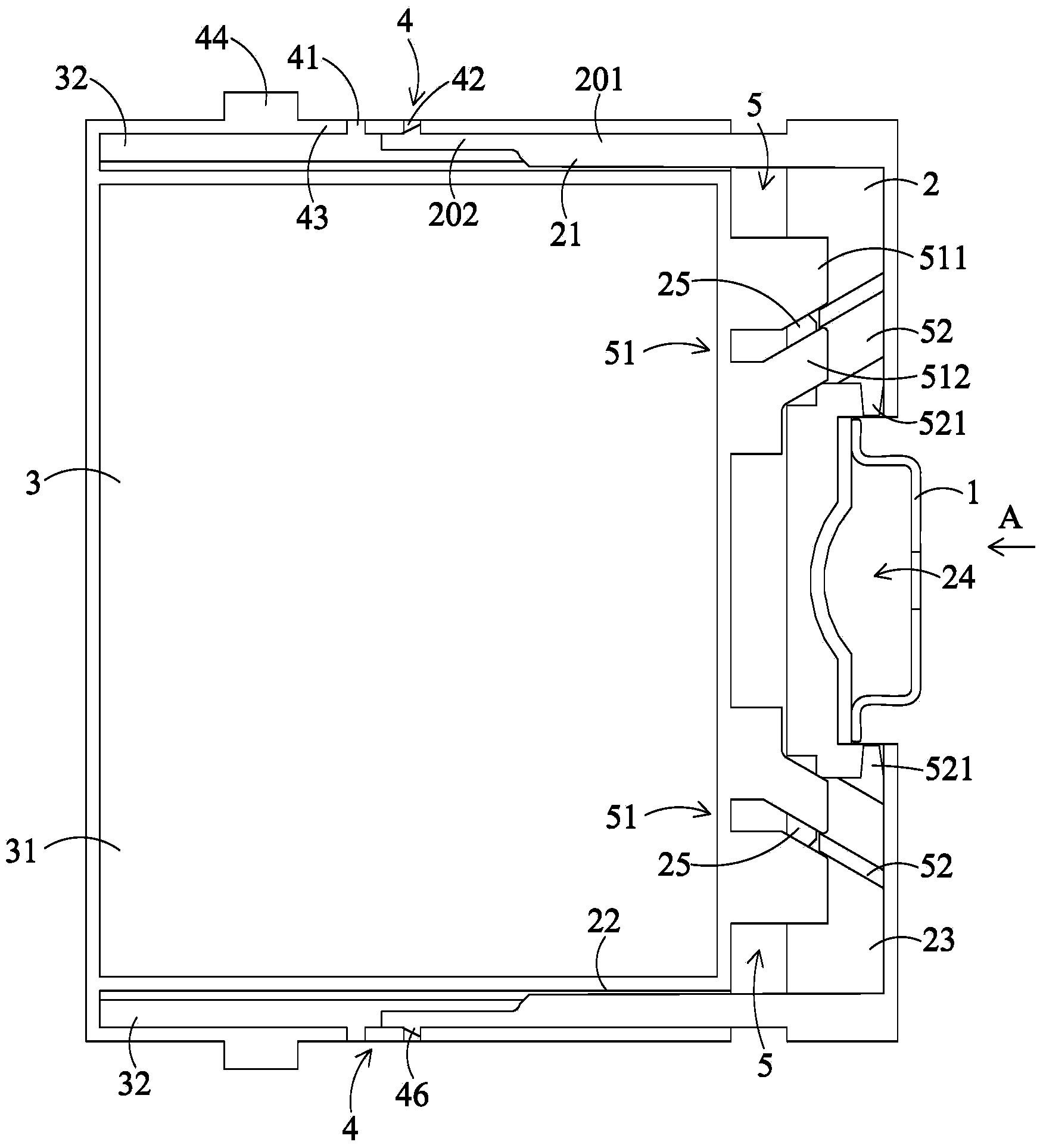
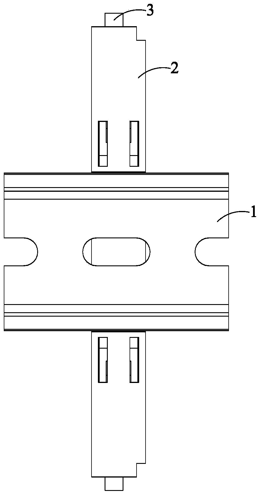
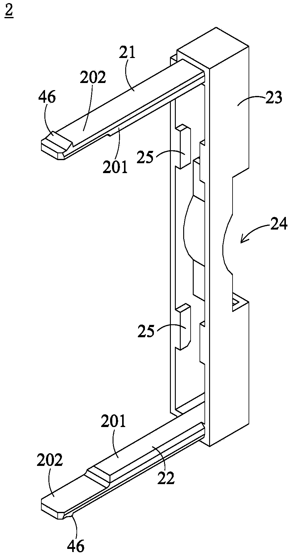
[0035] Such as figure 1 and figure 2 As shown, the guide rail fastening device of the present invention includes a guide rail 1 , a buckle 2 and a carrier 3 , and the buckle 2 detachably installs the carrier 3 on the guide rail 1 . In the present invention, the buckle 2 includes a first arm 21, a second arm 22, and a connecting body 23 connecting the first arm 21 and the second arm 22; 21 and the chute 32 of the second arm 22 , the chute 32 is provided with a locking structure 4 , and a wedge-shaped self-locking structure 5 is provided between the body 31 and...


PUM


Abstract

The invention discloses a guide rail clamping fixing device. The guide rail clamping fixing device comprises a guide rail, a clamping buckle and a bearing body; the clamping buckle comprises a first arm, a second arm, and a connecting body which connects the first arm with the second arm; the bearing body comprises a main body; chutes which are matched with the first arm and the second arm are arranged in two sides of the main body; clamping structures are arranged on the chutes; a wedge-shaped self-locking structure is arranged between the main body and the clamping buckle. According to the guide rail clamping fixing device, the chutes are matched and connected with the first arm and the second arm, and the clamping buckle and the bearing body are clamped and separated through the clamping structures; the clamping buckle and the guide rail are fixedly connected and disconnected through the wedge-shaped self-locking structure; therefore, the main body can be conveniently locked during assembling and can also be conveniently taken out by operating the clamping structures at two sides.

Description

technical field [0001] The invention relates to a guide rail fastening device. Background technique [0002] At present, there are many components that need to be fixed on the guide rail, especially in the fields of electrical, communication and numerical control, many controllers need to be installed side by side and fixed on a guide rail. In the existing structure, insufficient consideration is given to the convenience of disassembly and assembly of these fixtures (such as controllers), which leads to very inconvenient disassembly and assembly, which greatly affects work efficiency. Specifically, the rails in this structure are usually close to immovable objects, such as walls, cabinet walls, etc., and in the fields of electrical, communication and numerical control, there is usually an electrical connection between fixed objects (such as controllers). Sexual connection, its movement direction is limited, it is only convenient to extract in the axial direction. However, ...

Claims


Application Information

Patent Timeline
Patent Type & Authority Applications(China)
IPC IPC(8): B23Q3/00
CPCB25B11/00
Inventor 王晓轩
Owner OMRON SHANGHAI
Learn More