Electrosparking method

A processing method and electric spark technology, which can be used in electric processing equipment, metal processing equipment, manufacturing tools, etc., can solve the problems of prolonged production process, increased cost, and complicated process.

Inactive Publication Date: 2015-01-07
YANTAI POWER SUPPLY COMPANY OF STATE GRID SHANDONG ELECTRIC POWER +2
View PDF6 Cites 2 Cited by
  • Summary
  • Abstract
  • Description
  • Claims
  • Application Information

AI Technical Summary

Problems solved by technology

However, for workpieces with combined and complex structural requirements for the cavity structure, frequent replacement of forming tool electrodes is required, resulting in the disadvantages of prolonged production process, cumbersome process and increased cost

Method used


Image

  • Electrosparking method
  • Electrosparking method
  • Electrosparking method

Examples


Embodiment Construction

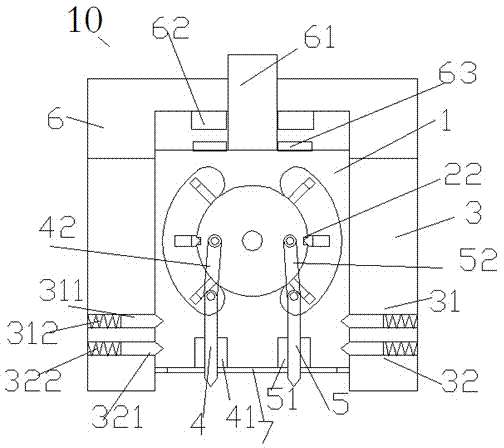
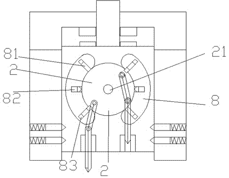
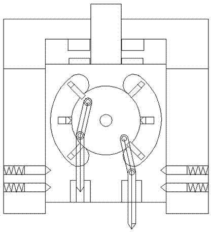
[0032] Refer below Figure 1-4 , the present invention is described in detail.

[0033]A kind of electrical discharge machining method, it uses a kind of electrical discharge machining head device 10, and described electrical discharge machining head device 10 comprises: lower frame 3, upper frame 6 and inner frame 1, and described upper frame 6 is in Above the lower frame 3, the inner frame 1 is located in the cavity formed by the lower frame 3 and the upper frame 6, and can slide up and down.

[0034] Wherein, the upper inner side of the upper frame 6 and the upper side of the inner frame 1 are respectively provided with coupled electromagnetic coils 62 and magnets 63 to drive the sliding of the inner frame 1; The lower part of the side wall is symmetrically provided with an upper wedge surface positioning pin 31 and a lower wedge surface positioning pin 32 in each side wall, and the lower parts of both sides of the inner frame 1 are respectively symmetrically provided with...


PUM


Abstract

Disclosed is an electrosparking method. An electrosparking head device (10) is used in the electrosparking method and comprises a lower rack (3), an upper rack (6) and an inner rack (1), the upper rack (6) is positioned above the lower rack (3), and the inner rack (1) is positioned in a cavity formed by the lower rack (3) and the upper rack (6) and can slide up and down.

Description

technical field [0001] The invention relates to the field of electrical discharge machining, in particular to an electrical discharge machining method. Background technique [0002] EDM is a special processing method that uses the electric erosion effect generated by the pulse discharge between the two electrodes immersed in the working fluid to erode conductive materials, also known as electric discharge machining or electric erosion machining. [0003] During EDM, the tool electrode and the workpiece are respectively connected to the two poles of the pulse power supply, and immersed in the working fluid, or the working fluid is filled into the discharge gap. The tool electrode is controlled to feed to the workpiece through the gap automatic control system. When the gap between the two electrodes reaches a certain distance, the pulse voltage applied to the two electrodes will break down the working fluid and generate spark discharge. A large amount of heat energy is concen...

Claims


Application Information

Patent Timeline
IPC IPC(8): B23H1/00B23H1/04B23H7/26
CPCB23H1/00B23H1/04B23H7/26
Inventor 张康
Owner YANTAI POWER SUPPLY COMPANY OF STATE GRID SHANDONG ELECTRIC POWER
Why Eureka
Try Eureka