Al technical title is built by PatSnap Al team. It summarizes the technical point description of the patent document.
A water tank wire drawing machine, vertical technology, applied in the field of vertical water tank wire drawing machine, can solve the problems of low safety performance, difficult maintenance, long auxiliary time, etc., achieve safe and convenient operation, improve drawing times, and compact structure Effect
Inactive Publication Date: 2015-01-07
SHANGHAI ZICHEN IND
View PDF5 Cites 3 Cited by
Summary
Abstract
Description
Claims
Application Information
AI Technical Summary
This helps you quickly interpret patents by identifying the three key elements:
Problems solved by technology
Method used
Benefits of technology
Problems solved by technology
[0002] At present, domestic water tank wire drawing machines are mostly flip-type water tank wire drawing machines. Drawing, tension, and wire take-up are independent of each other, occupying a large area, and inconvenient to operate and maintain.
The wire drawing machine for drawing steel wire mostly adopts a horizontal water tank wire drawing machine with 21 passes or 23 passes. Due to the limitation of the drawing passes, it is impossible to realize the thinner diameter steel wire required in the market in terms of technology. For example, drawing high-carbon thick steel wires of φ2.8mm or low-carbon thick steel wires to thin steel wires of φ0.11mm cannot be completed with existing wire drawing machines; moreover, it is difficult to thread wires into horizontal water tanks, and the auxiliary time is too long; in addition, the old-fashioned The drawing design of the water tank is open, and the safety performance is not high; because all the motors, transmission parts, and drawing tower wheels are installed on the same turning box, the stability of the equipment is not high, and the maintenance is difficult.
Method used
Image
Click on the blue label to locate the original text in one second.
Reading with bidirectional positioning of images and text.
Examples
Embodiment Construction
[0022] The present invention will be further described below in conjunction with the accompanying drawings and embodiments.
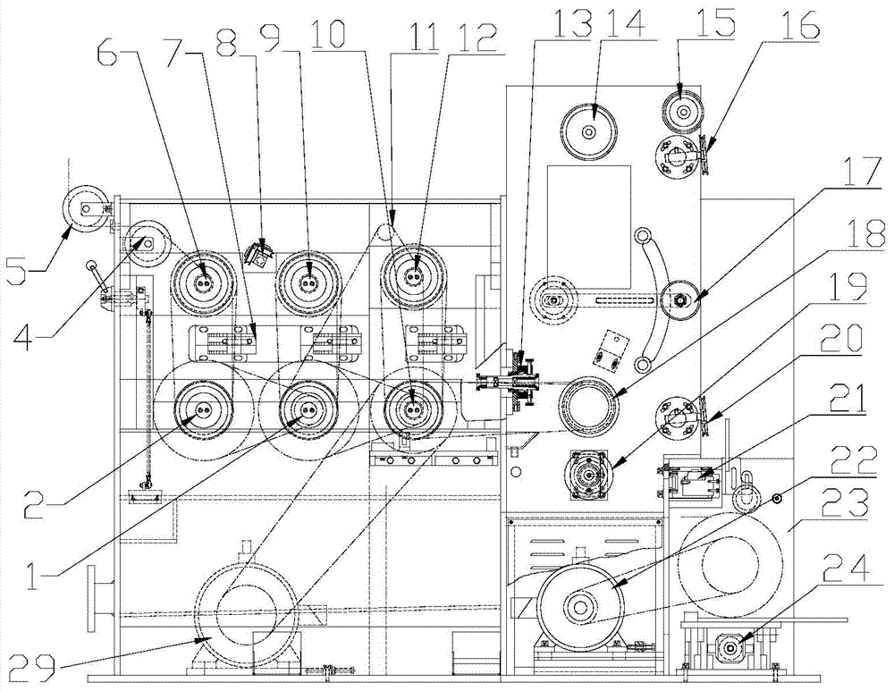
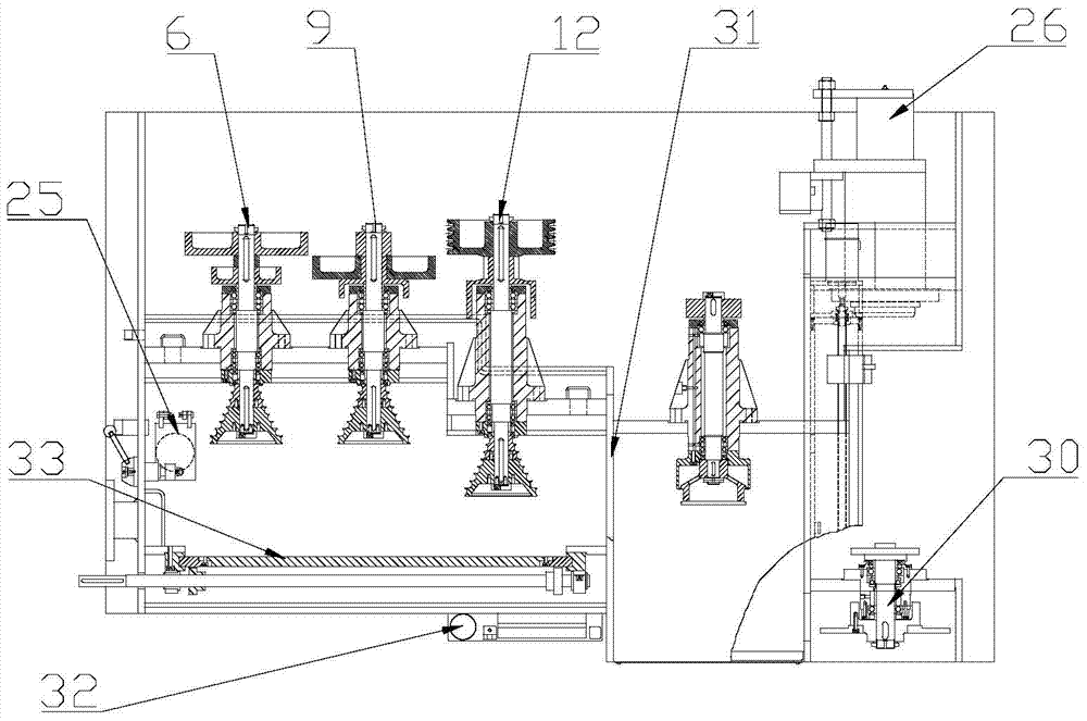
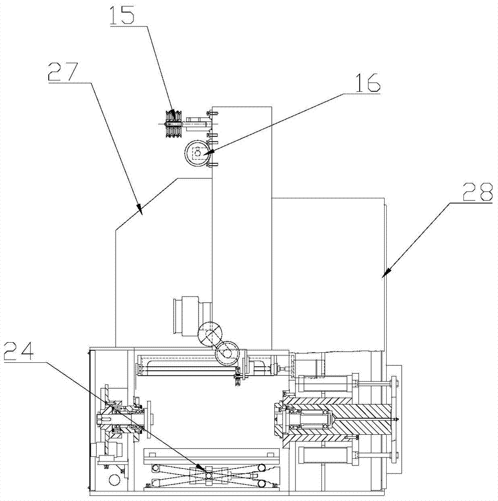
[0023] combine figure 1 , figure 2 with image 3 As shown, in this embodiment, the vertical water tank wire drawing machine includes several tower pulleys and corresponding wire drawing dies, a fine drawing die 13, a meter counting device 19, a traction wheel 18, a tension device 17, several wire passing devices, and a wire arranging device 17. Power device 29 and transmission device, the water tank wire drawing machine also includes a box body fixedly connected with the wire drawing machine frame, the tower pulley, the wire drawing die, the meter wheel, the traction wheel, the tension device, and several wire passing wheels The device, cable arrangement, power device and transmission device are all set in the box; the tower wheel includes three groups of tower wheels arranged in sequence, that is, the first tower wheel group (tape wheel group I), th...
PUM
Abstract
The invention discloses a vertical type water tank wire drawing machine. The vertical type water tank wire drawing machine comprises a plurality of cone pulleys and corresponding wire drawing moulds, one finish drawing mould assembly, a meter measuring device, a traction wheel, a tension device, a plurality of wire guiding devices, a wire arranging device, a power device and a transmission device which are arranged in one fixed box, wherein the cone pulleys comprise a cone pulley group I, a cone pulley group II and a cone pulley group III which are sequentially arranged, each cone pulley group comprises two cone pulleys which are correspondingly arranged up and down and are arranged on a driving shaft and a driven shaft, each driving shaft is arranged below while the corresponding driven shaft is arranged above, eight drawing grooves are formed in each cone pulley, a mould frame is arranged between the two cone pulleys, which are arranged up and down, in each cone pulley group, wire drawing moulds in eight passes are arranged in the drawing grooves corresponding to the cone pulleys in the mould frame and are sequentially arranged in a manner that the diameters of the moulds are gradually reduced, the finish drawing mould assembly is arranged corresponding to the cone pulley group III, and the pore diameter of a finish drawing mould in the finish drawing mould assembly is equal to the final diameter required by a steel wire finished product. The vertical type water tank wire drawing machine has the beneficial effects that the drawing passes are increased, thin steel wires can be drawn, wire threading time is short, starting safety performance is high, the whole structure is compact, floor space is small, and operational maintenance is facilitated.
Description
technical field [0001] The invention relates to the technical field of metal wire processing equipment, in particular to a vertical water tank wire drawing machine. Background technique [0002] At present, most domestic water tank wire drawing machines are flip-type water tank wire drawing machines. The wire drawing, tension and wire take-up are independent of each other, occupy a large area, and are inconvenient to operate and maintain. The wire drawing machine for drawing steel wire mostly adopts horizontal water tank wire drawing machine with 21 passes or 23 passes. Due to the limitation of drawing passes, it is impossible to realize the thinner diameter steel wire required in the market in terms of technology. For example, drawing high-carbon thick steel wires of φ2.8mm or low-carbon thick steel wires to thin steel wires of φ0.11mm cannot be completed with existing wire drawing machines; moreover, it is difficult to thread wires into horizontal water tanks, and the auxi...
Claims
Application Information
Patent Timeline
Application Date:The date an application was filed.
Publication Date:The date a patent or application was officially published.
First Publication Date:The earliest publication date of a patent with the same application number.
Issue Date:Publication date of the patent grant document.
PCT Entry Date:The Entry date of PCT National Phase.
Estimated Expiry Date:The statutory expiry date of a patent right according to the Patent Law, and it is the longest term of protection that the patent right can achieve without the termination of the patent right due to other reasons(Term extension factor has been taken into account ).
Invalid Date:Actual expiry date is based on effective date or publication date of legal transaction data of invalid patent.