


Quick Research
Generate reliable direction feasibility study reports for your R&D in just a few steps.

Technical Q&A
Discover and master advanced knowledge NOW. Basics, ideas, possibilities, all at once.

Find Solutions
As an expert in R&D theories, this can generate solutions to your technical problems instantly.

Evaluate Feasibility
Analyze your overall solution with one click, know your potential R&D risks in advance.

Monitor Landscape
Get weekly tech updates, stay abreast of the latest tech innovations and key insights.
brake control device
A technology of brake control and cylinder device, which is applied in the direction of brake transmission device, hydraulic brake transmission device, brake action activation device, etc., to achieve the effect of improving the change of rigidity
- Summary
- Abstract
- Description
- Claims
- Application Information
AI Technical Summary
Problems solved by technology
Method used
Image

Examples
no. 1 approach >
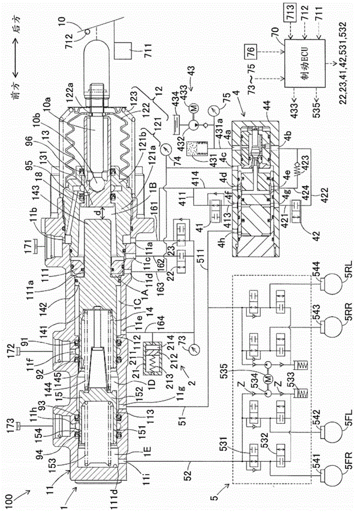
[0030] will refer to the attached Figure 1 to Figure 3 A brake control device according to a first embodiment of the present invention will be described. figure 1 is a view explaining the overall structure of the master cylinder device 100 including the brake control device according to the first embodiment of the present invention. The master cylinder device 100 is installed in a hybrid vehicle and is used together with a regenerative braking device (not used) to form a braking system of the hybrid vehicle. like figure 1 As shown, the master cylinder device 100 is mainly composed of the master cylinder 1, the force generating device 2, the separation lock valve 22, the force valve 23, the servo hydraulic pressure generating device 4, the hydraulic control unit 5, the brake ECU 70 and various sensors 11 to 713 And 73 to 76 formed.
[0031] The master cylinder 1 supplies working fluid to the hydraulic control part 5 and is mainly formed of a master cylinder part 11 , a head...
Embodiment approach
[0107] In addition, according to the first embodiment of the present invention, the master cylinder hydraulic pressure in the first pressure chamber 1D is fed back to the fourth chamber 4E of the servo hydraulic pressure generating device 4 . Still further, the servo hydraulic pressure generating device 4 may supply the servo hydraulic pressure (drive hydraulic pressure) corresponding to the master cylinder hydraulic pressure to the servo chamber 1A, or in other words, the servo hydraulic pressure in response to the depression amount of the brake pedal 10 during the adjustment mode operation. As opposed to conventional techniques, the actuation of the first and second master pistons can be assisted even during regulation mode operation by using the servohydraulic generating device 4 to improve the response of the braking force.
[0108] It should be noted here that, instead of using the feedback supply of the master cylinder hydraulic pressure, the hydraulic pressure in respons...
no. 2 approach >
[0110] Next, refer to Figure 4 A second embodiment of the brake control device according to the present invention having a structure different from that of the master cylinder device 100A will be described. Figure 4 is a view illustrating an overall structure of a master cylinder device 100A including a brake control device according to a second embodiment of the present invention. The master cylinder device 100A is installed in a hybrid vehicle and forms a braking system for the hybrid vehicle together with a regenerative actuator (not shown).
[0111]The master cylinder device 100A includes a master cylinder 110A for pressurizing working fluid. The operator of the vehicle depresses the brake pedal 10F connected to the master cylinder 110A to operate the master cylinder 110A. The master cylinder 110A generates master cylinder hydraulic pressure by pressurizing working fluid therein, and thus supplies the generated master cylinder hydraulic pressure to the hydraulic pressu...
PUM
 Abstract
Description
Claims
Application Information
 - R&D Engineer
- R&D Manager
- IP Professional
- Industry Leading Data Capabilities
- Powerful AI technology
- Patent DNA Extraction
Browse by: Latest US Patents, China's latest patents, Technical Efficacy Thesaurus, Application Domain, Technology Topic, Popular Technical Reports.
© 2024 PatSnap. All rights reserved.Legal|Privacy policy|Modern Slavery Act Transparency Statement|Sitemap|About US| Contact US: help@patsnap.com