Micro-electromechanical reflector and method for manufacturing micro-electromechanical reflector

A reflector and micro-electromechanical technology, which is applied in the manufacture of micro-structure devices, processes for producing decorative surface effects, micro-structure technology, etc., can solve problems such as difficulty in deriving heat from the substrate, restrictions on the freedom of movement of electrodes or micro-mirrors, etc. , to achieve a stable conductive connection surface and improve the effect of precision

Active Publication Date: 2014-12-31
ROBERT BOSCH GMBH
View PDF11 Cites 2 Cited by
  • Summary
  • Abstract
  • Description
  • Claims
  • Application Information

AI Technical Summary

Problems solved by technology

This can lead to limitations in the choice of possible electrode geometries, which in turn can lead to limitations in the degrees of freedom of movement of the electrodes or micromirrors
Furthermore, the mechanical suspension along the torsion axis is often fabricated from polysilicon layer structures or oxide layer structures, whereby the heat that occurs at the mirror surface by radiation can be difficult to dissipate into the substrate

Method used


Image

  • Micro-electromechanical reflector and method for manufacturing micro-electromechanical reflector
  • Micro-electromechanical reflector and method for manufacturing micro-electromechanical reflector
  • Micro-electromechanical reflector and method for manufacturing micro-electromechanical reflector

Examples


Embodiment Construction

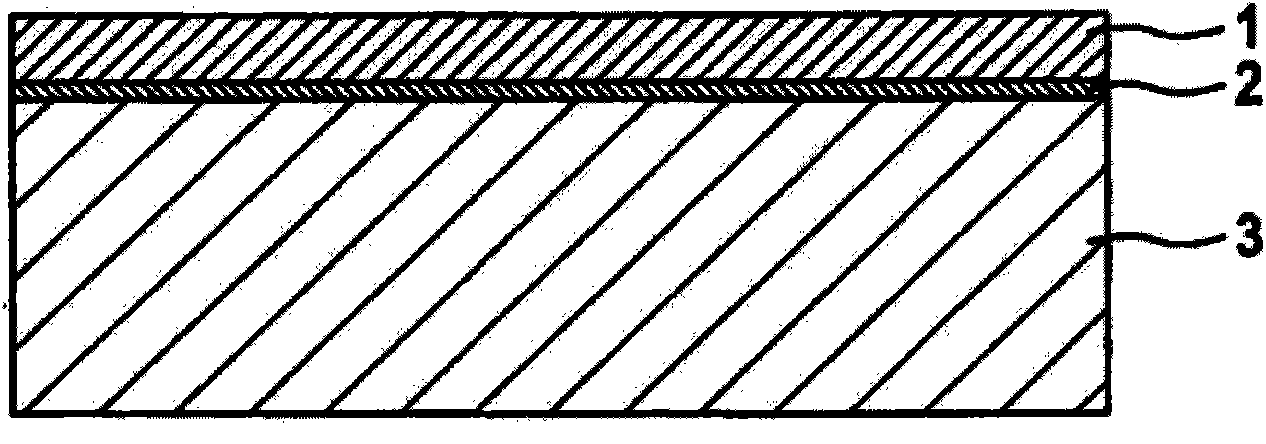
[0047] figure 1 A schematic diagram of a first intermediate product in the manufacture of a microelectromechanical reflector is shown in cross-section. In this case, the electrode substrate 3 can be provided with an oxide layer 2 which is applied to the surface of the electrode substrate 3 . A monocrystalline silicon layer 1 can then be applied on the oxide layer 2 . In one embodiment variant, the monocrystalline silicon layer 1 can be the first functional layer on a silicon-on-insulator wafer ("silicon an insulator: SOI wafer") as electrode substrate 3 .

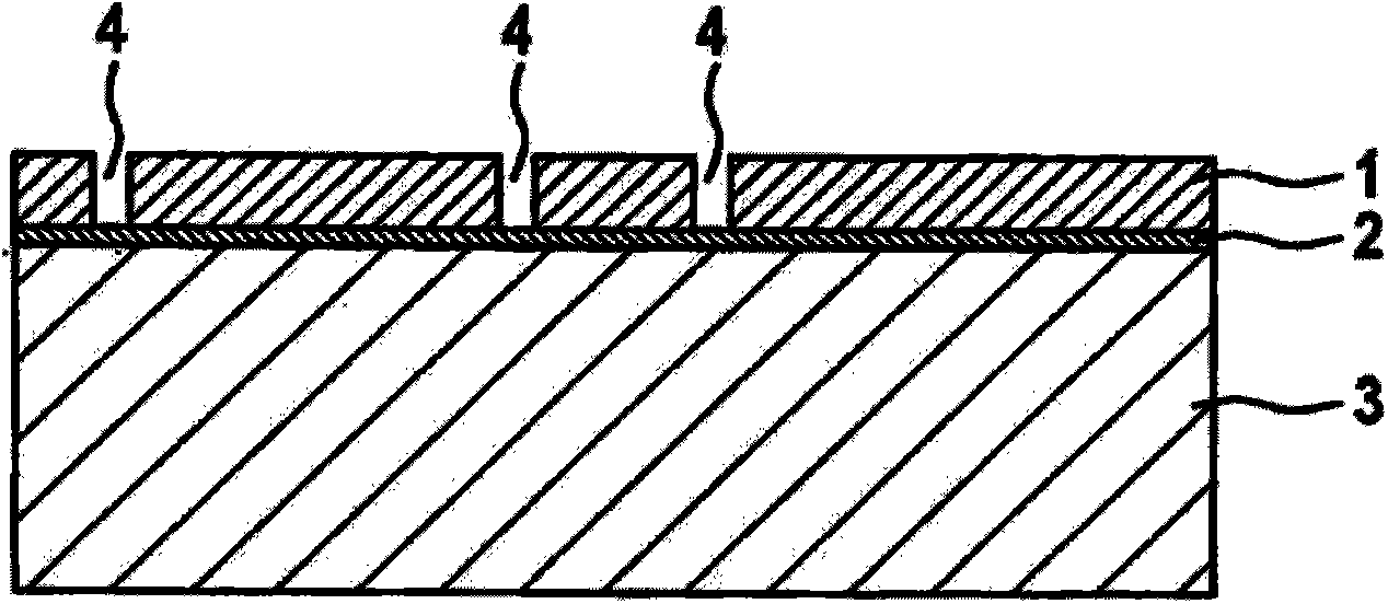
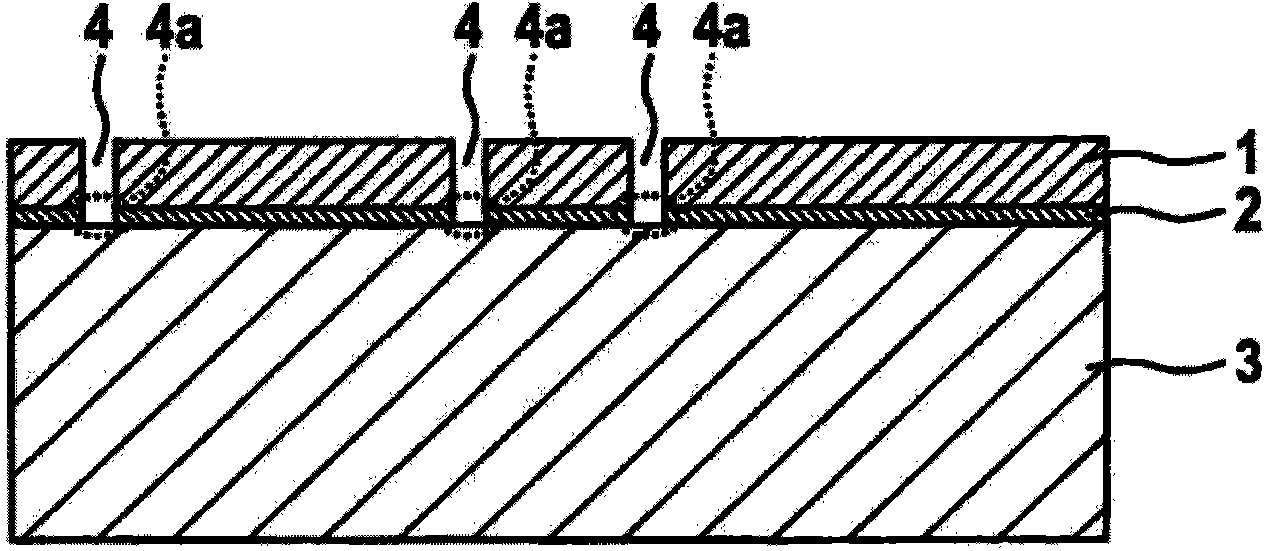
[0048] Such as figure 2 As shown, a via (Vias ("vertical interconnect access (vertical interconnect channel)") or a trench 4 can be provided in the monocrystalline silicon layer 1, which extends down to the oxide layer 2. As image 3 As shown, the oxide layer 2 is etched in the region of the via bottom or trench bottom 4 a, likewise up to the electrode substrate 3 .

[0049] Figure 4 Schematic showing one intermediat...


PUM


Abstract

The invention relates to a micro-electromechanical reflector, including an electrode substrate having first and second surfaces opposite to the first surface, on whose first surface a monocrystalline silicon layer is situated, a plurality of electrode recesses, which are introduced from the second surface into the electrode substrate, at least one torsion spring structure, which is implemented in the monocrystalline silicon layer above one of the electrode recesses, a carrier substrate, which is applied to the second surface of the electrode substrate, and a reflector surface situated on the monocrystalline silicon layer. At least one first electrode, movably mounted in the electrode substrate via the torsion spring structure, and at least one second electrode, mechanically fixedly anchored to the carrier substrate and the monocrystalline silicon layer, are formed by the electrode recesses. The electrode surfaces of the first and second electrodes are situated in parallel to one another and perpendicularly to the electrode substrate surfaces.

Description

technical field [0001] The invention relates to a microelectromechanical reflector and a method for producing a microelectromechanical reflector, in particular in the field of capacitively operated microelectromechanical reflectors. Background technique [0002] Miniaturized mirrors are used in different applications, for example, optics for portable telecommunication equipment. These mirrors—often also called micromirrors here—can be produced from microelectromechanical structures (MEMS, “micro-electromechanical systems”). [0003] Such a micromirror can be based on the capacitive operating principle, which means that two electrode elements arranged relative to one another in a predetermined geometry are acted upon with a voltage. Movement of the electrodes relative to each other can be induced by varying this voltage. In this case, usually one of the electrodes is fastened to the substrate, while the other of the electrodes is freely movable relative to the substrate wit...

Claims


Application Information

Patent Timeline
Patent Type & Authority Applications(China)
IPC IPC(8): G02B26/08B81C1/00
CPCG02B26/0841Y10T29/49155
Inventor J·赖因穆特
Owner ROBERT BOSCH GMBH
Why Eureka
Try Eureka