
Marking devices for switchgear and other electrical installations

A technology for identification devices and electrical devices, which is applied in the directions of identification devices, instruments, stamps, etc., can solve the problems of inclined installation and loss of signs, and achieves the effect of preventing wrong installation, reducing errors, and reducing the risk of loss.

Active Publication Date: 2016-12-14
PHOENIX CONTACT GMBH & CO KG
View PDF5 Cites 0 Cited by
  • Summary
  • Abstract
  • Description
  • Claims
  • Application Information

AI Technical Summary

Problems solved by technology

A disadvantage of the known marking devices is that the sign usually has to have precisely defined dimensions, since the bearing surfaces and support surfaces are exactly matched to a correspondingly designed sign
Furthermore, in the case of the known marking device, if an installation error occurs, for example if one side of the sign is wrongly pushed under the provided supporting surface during installation, the sign may be inserted at an angle
In this case the installation must be re-implemented, otherwise there is a risk of loss due to the problem not being discovered

Method used


Image

  • Marking devices for switchgear and other electrical installations
  • Marking devices for switchgear and other electrical installations
  • Marking devices for switchgear and other electrical installations

Examples


Embodiment Construction

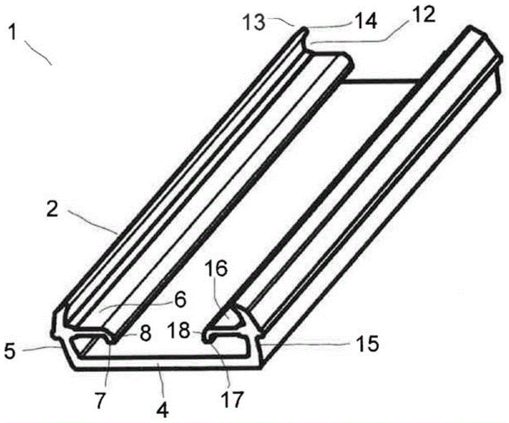
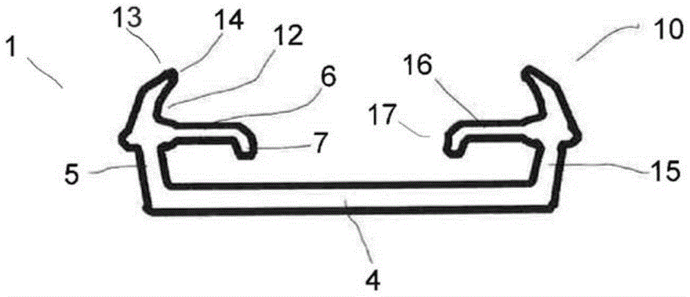
[0038] first combined with Figures 1 to 3 A first embodiment of the identification device of the present invention will be described. The marking device 1 of the present invention comprises a bracket profile 2 and at least one sign 3 (see image 3 ).

[0039] The marking device 1 according to the invention is used in a switchgear 100 and other electrical installations and other equipment, and is fastened on the switchgear 100 with the bracket profile 2 . The fastening can be realized by bonding, screwing, riveting or other fastening methods.

[0040] figure 1 The support profile 2 shown in a perspective view has a rear profile or rear wall 4 , as well as two retaining walls 5 and 15 arranged here on the sides, which together form the approximate contour of the support profile 2 . U-shaped outer cross-section.

[0041] A support lug 6 extending transversely to the holding wall 5 is fastened to the holding wall 5 . On the holding wall 15 there is provided a support lug 16...


PUM


Abstract

The invention relates to a marking device (1) for switch cabinets (100) and other electrical devices, comprising a bracket profile (2) and a sign (3). The support profile (2) is adapted and constructed for receiving the label (3). The carrier profile (2) has a rear wall (4) and two lateral retaining walls (5, 15) extending forward from the rear wall (4). Supporting tabs (6, 16) for supporting the label (3) are provided on the support profile (2) and extend transversely to the holding wall (5, 15). A downward insertion protection device (7, 17) is provided to prevent the label (3) from being inserted under the supporting piece (6, 16) during installation.

Description

technical field [0001] The invention relates to a marking device for switch cabinets and other electrical installations and for plant engineering. Background technique [0002] Various identification devices for switch cabinets are disclosed in the prior art, so as to install a label for accurate identification on the switch cabinet. A disadvantage of the known marking devices is that the labels generally have to have precisely defined dimensions, since the support surfaces and support surfaces are exactly matched to a correspondingly designed label. Furthermore, in the case of known marking devices, when an installation error occurs, for example when one side of the sign is mistakenly pushed below the provided supporting surface during installation, the sign may be inserted obliquely. In this case, the installation must be re-performed, otherwise there is a risk of loss due to the problem not being discovered. Contents of the invention [0003] It is therefore the objec...

Claims


Application Information

Patent Timeline
Patent Type & Authority Patents(China)
IPC IPC(8): G09F3/20
CPCG09F3/204G09F3/16G09F3/18
Inventor 海因茨·赖布克托马斯·珀尔克
Owner PHOENIX CONTACT GMBH & CO KG
Learn More