
A safe power supply device

A power supply and safety technology, which is applied in the direction of coupling devices, components of connecting devices, circuits, etc., can solve problems such as poor contact, looseness, and low safety awareness, and achieve the effect of avoiding damage and preventing loosening

Active Publication Date: 2021-03-23
国网山东省电力公司单县供电公司
View PDF5 Cites 0 Cited by
  • Summary
  • Abstract
  • Description
  • Claims
  • Application Information

AI Technical Summary

Problems solved by technology

[0002] In the field of electric power supply, the plug-in device is one of the indispensable accessories of electric equipment, but the pins of the existing plug-in plug are exposed, easily damaged and deformed, resulting in poor contact, and it is difficult to ensure the stability of the electrical connection ;The existing structure is not safe enough for some people with low safety awareness and low cognitive ability, such as children, because they are more curious, exploring, and playful, and it is impossible for parents to watch their children all the time, so , When the parents are not paying attention, they will use metal rods, keys and the like to insert into the jack, and such behavior will cause electric shock accidents, which will cause great harm to the human body and cause death in severe cases. The traditional There is a great potential safety hazard in the plug-in device; the plug has poor stability during use and is easily loosened by dragging and pulling, resulting in poor circuit contact and affecting the normal use of electrical equipment

Method used


Image

  • A safe power supply device
  • A safe power supply device
  • A safe power supply device

Examples


Embodiment Construction

[0020] In order to clearly illustrate the technical features of the present solution, the present invention will be described in detail below through specific implementation methods and in conjunction with the accompanying drawings. The following disclosure provides many different embodiments or examples for implementing different structures of the present invention. To simplify the disclosure of the present invention, components and arrangements of specific examples are described below. Furthermore, the present invention may repeat reference numerals and / or letters in different instances. This repetition is for the purpose of simplicity and clarity and does not in itself indicate a relationship between the various embodiments and / or arrangements discussed. It should be noted that components illustrated in the figures are not necessarily drawn to scale. Descriptions of well-known components and processing techniques and processes are omitted herein to avoid unnecessarily lim...


PUM


Abstract

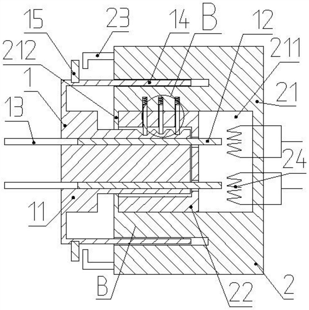
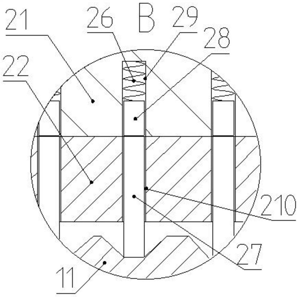
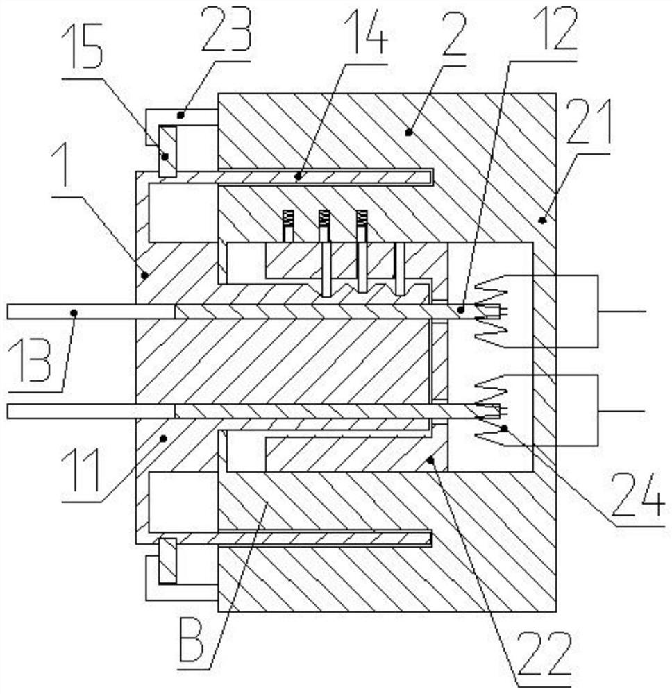
The invention discloses a high-power electric power supply device. The device comprises a plug and a socket; the plug comprises an insulator, insertion pins and wires; the socket comprises a socket body and elastic sheets; the socket further comprises a socket core; a guide hole is formed in the socket; the socket core is arranged in the guide hole; the opening of the guide hole is provided with acover plate; insertion holes which are shaped to match the insulator are formed in the cover plate and the socket core; elastic grooves b are formed in the side surface of the socket core; elastic grooves a are formed in the inner wall of the guide hole; elastic units b are arranged in the elastic grooves b; springs and elastic units b are arranged in the elastic grooves a; the springs are arranged at the bottoms of the elastic grooves a; when the socket core is attached to the cover plate, the elastic grooves b are aligned with the elastic grooves a; grooves are formed in the surface of theinsulator; when the insulator is inserted into the bottom of the insertion hole of the socket core, the elastic units a are in the grooves of the insulator, the elastic units a are all in the elasticgrooves b; and the elastic units b are all arranged in the elastic grooves a. The electric power supply device is unlikely to be loosened; the insertion pins of the electric power supply device have little possibility of being damaged; and erroneous insertion connection can be prevented.

Description

technical field [0001] The invention relates to the technical field of electric power supply equipment, in particular to an electric power supply device with high safety. Background technique [0002] In the field of electric power supply, the plug-in device is one of the indispensable accessories of electric equipment, but the pins of the existing plug-in plug are exposed, easily damaged and deformed, resulting in poor contact, and it is difficult to ensure the stability of the electrical connection ;The existing structure is not safe enough for some people with low safety awareness and low cognitive ability, such as children, because they are more curious, exploring, and playful, and it is impossible for parents to watch their children all the time, so , When the parents are not paying attention, they will use metal rods, keys and the like to insert into the jack, and such behavior will cause electric shock accidents, which will cause great harm to the human body and cause...

Claims


Application Information

Patent Timeline
Patent Type & Authority Patents(China)
IPC IPC(8): H01R13/642H01R13/15H01R13/639H01R13/56
CPCH01R13/15H01R13/56H01R13/639H01R13/642
Inventor 张旺苏启征祝凤兰王晨光孙洁马庆朋陈颖杨星鲁克侯洁仇世邦于建兴刘鹏常金国高妍陈鹏王磊
Owner 国网山东省电力公司单县供电公司
Learn More