Stroke simulator

A stroke simulator and simulator technology, which is applied in the directions of brakes, braking action starting devices, vehicle components, etc., can solve problems such as hindering the piston from leaving, hindering the displacement of the travel simulator, and achieve the effect of smooth action.

Active Publication Date: 2014-12-24
HONDA MOTOR CO LTD +1
View PDF6 Cites 2 Cited by
  • Summary
  • Abstract
  • Description
  • Claims
  • Application Information

AI Technical Summary

Problems solved by technology

Furthermore, when the closed space is filled with brake fluid, a negative pressure is generated in the closed space when the piston leaves the holder, and this negative pressure prevents the piston from leaving the holder and prevents displacement of the stroke simulator.

Method used


Image

  • Stroke simulator
  • Stroke simulator
  • Stroke simulator

Examples


Embodiment Construction

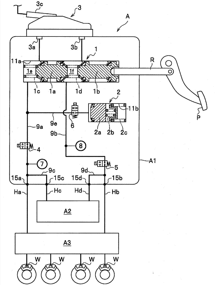
[0028] Hereinafter, embodiments of the present invention will be described in detail with reference to the drawings as appropriate. figure 1 It is a schematic configuration diagram of a vehicle brake system according to an embodiment of the present invention.

[0029] figure 1 The shown vehicle brake system A includes a By-Wire brake system that operates when a prime mover (engine, motor, etc.) Both of the brake systems, the vehicle brake system A includes: a main hydraulic cylinder device A1 that generates brake hydraulic pressure by the pedal force when the brake pedal (brake operating member) P is depressed; shown) a motor hydraulic cylinder device A2 that generates brake hydraulic pressure; and a vehicle stability assist device A3 (hereinafter referred to as "hydraulic control device A3") that supports stabilization of vehicle behavior. The master cylinder device A1 , the motor cylinder device A2 , and the hydraulic control device A3 are configured as independent units a...


PUM


Abstract

Provided is a stroke simulator in which a piston is displaced and causes an elastic member to elastically deform so as to block a space in which the elastic member is housed, and wherein the piston moves smoothly without the displacement thereof being obstructed by negative pressure formed in the blocked space. A stroke simulator, in which a simulator piston (2a), which is displaced within a cylinder section (200) due to the operation of a braking operation element by a driver, presses a first return spring (2b), which is stored inside a cylindrical tube section (224d) that has a base, from the opening section (224d2) side of the cylindrical tube section (224d), causing the first return spring (2b) to elastically deform, and generating braking reactive force. When the opening section (224d2) is blocked by the simulator piston (2a), brake fluid which fills the inside of the cylinder section (200) is taken into the inside of the cylindrical tube section (224d) via a flow channel (224d1) which passes from a second cylinder (202) to the inside of the cylindrical tube section (224d).

Description

technical field [0001] The invention relates to a travel simulator for generating a braking reaction force for application to a brake pedal of a braking device. Background technique [0002] There is widely known a brake device (electric brake device) that uses an electric motor as a drive source of a booster that boosts the pedaling force when the brake pedal is stepped on. Such an electric brake device includes a stroke simulator that simulates a brake reaction force on a brake pedal depressed by a driver (see Patent Document 1). [0003] It is required that the stroke simulator give the driver the same operating feeling (operating feeling) as that of a conventional brake pedal operated by brake fluid (brake fluid). Therefore, a stroke simulator is disclosed, which is configured to apply the elastic force (reaction force) generated by the elastic deformation of two elastic members with different elastic coefficients to the brake pedal as the brake reaction force, correspo...

Claims


Application Information

Patent Timeline
Patent Type & Authority Applications(China)
IPC IPC(8): B60T8/17
CPCB60T8/409B60T7/042B60T8/368B60T8/4086B60T13/146B60T13/662B60T13/686B60T15/36
Inventor 村山一昭铃木治朗中村元泰
Owner HONDA MOTOR CO LTD
Why Eureka
Try Eureka