Optical fiber interconnection system and method

An interconnection system and optical fiber technology, applied in the coupling of optical waveguides, fiber mechanical structures, instruments, etc., can solve problems such as inability to withstand harsh environments, defects, and installation that cannot be found in time

Inactive Publication Date: 2014-12-24
TYCO ELECTRONICS (SHANGHAI) CO LTD
View PDF5 Cites 7 Cited by
  • Summary
  • Abstract
  • Description
  • Claims
  • Application Information

AI Technical Summary

Problems solved by technology

When actually installing the fiber jumper, most operators need to complete three steps: first, check the fiber jumper installation list, then visually identify the fiber jumper number, and finally find the corresponding installation port to insert the fiber jumper; each step requires the operator to be careful Recognizing text can easily cause visual fatigue; while numbered labels or printing often have problems such as blurred and / or missing handwriting and cannot withstand factors such as harsh environments, and even the lighting effects on the installation site will affect the recognition and judgment of operators, etc.
At the same time, the on-site operators cannot find out in time if there is a wrong installation, and the post-maintenance of the fiber jumper and the change of the fiber jumper interconnection will also encounter the above-mentioned inconvenience

Method used


Image

  • Optical fiber interconnection system and method
  • Optical fiber interconnection system and method
  • Optical fiber interconnection system and method

Examples


Embodiment Construction

[0067] The technical solutions of the present invention will be further specifically described below through the embodiments and in conjunction with the accompanying drawings. In the specification, the same or similar reference numerals designate the same or similar components. The following description of the embodiments of the present invention with reference to the accompanying drawings is intended to explain the general inventive concept of the present invention, but should not be construed as a limitation of the present invention.

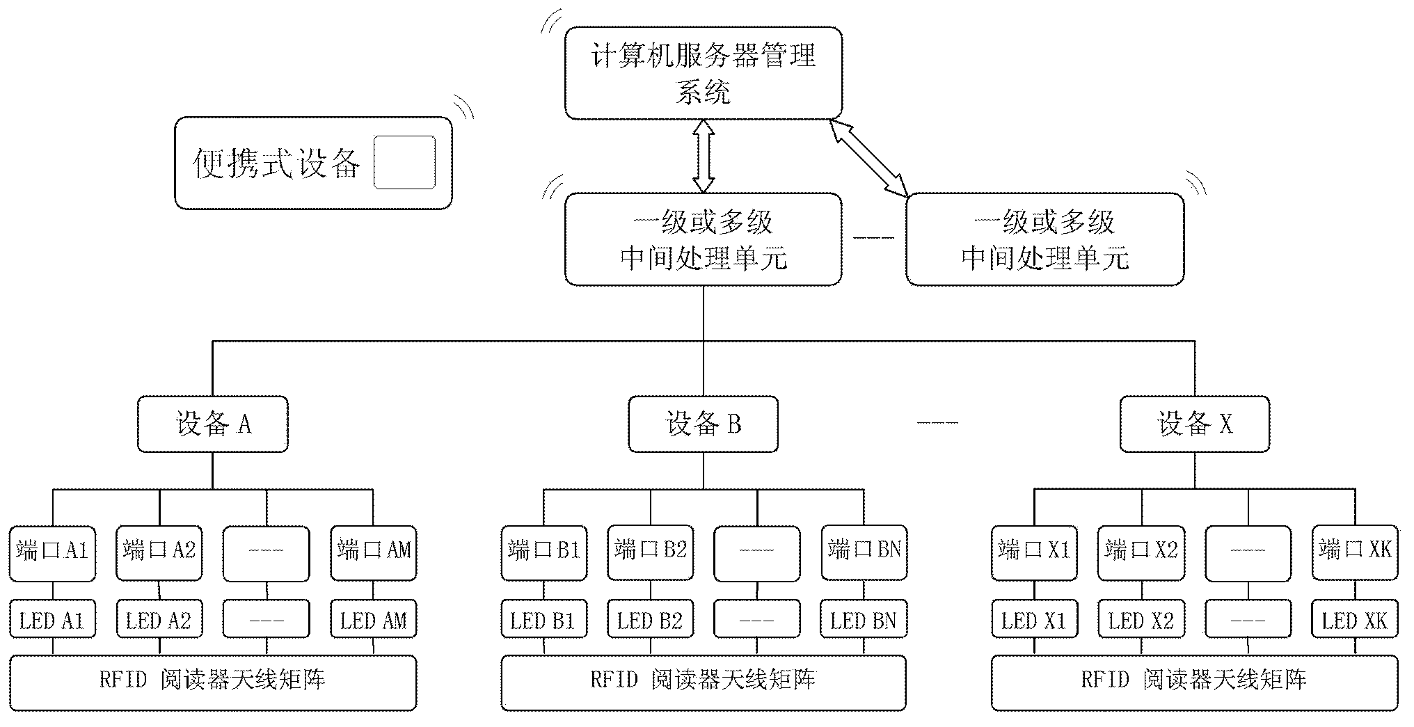
[0068] figure 1 A schematic structural diagram of an optical fiber distribution system according to an exemplary embodiment of the present invention is shown.

[0069] Such as figure 1 As shown, the entire optical fiber distribution system mainly includes multiple independent devices (referred to as objects herein), such as device A, device B, . . . , device X.

[0070] Such as figure 1 As shown, each device has a plurality of ports for conn...


PUM


Abstract

The invention discloses an optical fiber interconnection system that is used for establishing optical fiber interconnection among a plurality of objects. The system comprises at least one optical fiber, a plurality of readers, a plurality of indicators, and a server management system. To be specific, labels are respectively integrated at two ends of each optical fiber; and identical and unique matching codes or different matching codes in a one-to-one correspondence mode are respectively written into the two labels of each optical fiber. The plurality of readers are respectively arranged at to-be-connected ports of all objects and are used for reading the matching codes written into the labels of the optical fibers of all ports. The multiple indicators are respectively arranged at to-be-connected ports of all objects and are used for displaying the states of the corresponding ports. And the server management system is used for carrying out processing on data read from the objects and controlling the indication states of the indicators. In addition, the invention also provides a method for establishing optical fiber interconnection among multiple objects. With utilization of the server management technology, the label identification technology, and the different indication states of the indictors, the field operator can be guided to install the jumper fiber at the right place accurately based on the different indication states of the indicators.

Description

technical field [0001] The present invention relates to a system and method for establishing correct optical fiber interconnection between multiple devices or different areas of the same device, in particular to a system and method for intelligently batch-installing fiber jumpers. [0002] The invention is mainly applied to the installation and maintenance of fiber jumpers in optical fiber distribution systems, especially the batch installation of fiber jumpers. Background technique [0003] The traditional jumper wiring system distinguishes the jumper by the serial number label or printing attached to each jumper, and the identification of the connection port also depends on the port number label or printing, and some products do not even design the port number Rely only on sequence distinction. When actually installing the fiber jumper, most operators need to complete three steps: first, check the fiber jumper installation list, then visually identify the fiber jumper num...

Claims


Application Information

Patent Timeline
Patent Type & Authority Applications(China)
IPC IPC(8): G02B6/44G02B6/38G06K17/00
CPCH04Q1/136
Inventor 朱槐圣童朝阳张伟利
Owner TYCO ELECTRONICS (SHANGHAI) CO LTD
Why Eureka
Try Eureka