
Electromagnetic Action Dynamometer

An electromagnetic actuation and dynamometer technology, applied in power metering, measuring devices, instruments, etc., can solve problems such as easy leakage of hydraulic system seals, difficulty in improving position control accuracy, pollution of hydraulic oil environment, etc. Effects of maintenance costs, simple wiring, small environmental pollution and noise

Active Publication Date: 2016-12-07
浙江孔辉汽车科技有限公司
View PDF4 Cites 0 Cited by
  • Summary
  • Abstract
  • Description
  • Claims
  • Application Information

AI Technical Summary

Problems solved by technology

There are many inherent defects and deficiencies in the hydraulic drive mode, which are specifically manifested in: ①The seal of the hydraulic system is prone to leakage, the hydraulic oil is easy to pollute the environment, and the problem of waste disposal is even more serious; ②The hydraulic pressure is easily polluted and needs regular maintenance and replacement. High cost; ③It is difficult to improve the accuracy of position control, which requires expensive positioning sensors and precise electro-hydraulic valves. There are creep trends, hysteresis, and blind spots in the movement, and pressure and temperature changes make the control more complicated; ④The role of hydraulic pump source The disadvantage of high noise

Method used


Image

  • Electromagnetic Action Dynamometer
  • Electromagnetic Action Dynamometer
  • Electromagnetic Action Dynamometer

Examples


Embodiment Construction

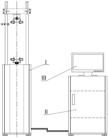
[0021] Such as figure 1 As shown: the dynamometer includes a main part I, a control cabinet II connected to the main part I, and a host computer PC III connected to the control cabinet II. It is characterized in that the main part I uses two symmetrically arranged linear motors as power source, a linear encoder is used for the position closed-loop control of the linear motor, and a proximity switch is used for the stroke limit control of the linear motor.

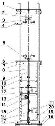
[0022] Such as figure 2 , 3 , 4, 5, 6, and 7: the main part I includes: top guide post fixing seat 1, force sensor 2, shock absorber upper end fixing seat 3, temperature sensor fixing bracket 4, shock absorber lower end fixing seat 5. Upper fixing plate 6, upper guide plate 7, left linear motor stator 8a, right linear motor stator 8b, sliding part 9, upper stator pressure plate 10, left and right linear motor movers 11, linear encoder 12, middle stator pressure plate 13 , grating probe 14, limit block 15, proximity swit...


PUM


Abstract

The invention relates to a device for testing the performance of a shock absorber, specifically an electromagnetically actuated dynamometer. The dynamometer includes a main part I, a control cabinet II connected to the main part I, and a control cabinet II connected to the The upper computer PCⅢ is characterized in that: the main part I uses two symmetrically arranged linear motors as the power source, a linear encoder is used as the position closed-loop control of the linear motor, and a proximity switch is used for the linear motor. The stroke limit control of the motor can meet the high-performance test requirements of shock absorbers of different models. The present invention is obviously superior to the electromagnetic actuated dynamometer with the existing structural mode in terms of precision, installation, maintenance, environmental pollution and noise.

Description

technical field [0001] The invention relates to a device for testing the performance of a shock absorber, specifically an electromagnetically actuated dynamometer. The dynamometer uses a linear servo motor as a power source and adopts an all-position closed-loop motion control method for vibration reduction. The motion control of the shock absorber can meet the high-performance test requirements of shock absorbers of different models. Background technique [0002] At present, the power source of the existing dynamometer in China adopts the hydraulic cylinder drive mode. There are many inherent defects and deficiencies in the hydraulic drive mode, which are specifically manifested in: ①The seal of the hydraulic system is prone to leakage, the hydraulic oil is easy to pollute the environment, and the problem of waste disposal is even more serious; ②The hydraulic pressure is easily polluted and needs regular maintenance and replacement. High cost; ③It is difficult to improve t...

Claims


Application Information

Patent Timeline
Patent Type & Authority Patents(China)
IPC IPC(8): G01L3/24
Inventor 吕济明李忠岩郭耀华郭弓
Owner 浙江孔辉汽车科技有限公司
Learn More