
Wave direction detection device of wave buoy

A verification device and wave buoy technology, applied in measurement devices, instruments, etc., can solve problems such as horizontal acceleration interference, achieve the effects of simple structure design, improve maintainability and reliability, and avoid horizontal acceleration interference

Active Publication Date: 2014-12-24
中船鹏力(南京)大气海洋信息系统有限公司
View PDF6 Cites 4 Cited by
  • Summary
  • Abstract
  • Description
  • Claims
  • Application Information

AI Technical Summary

Problems solved by technology

However, the existing recognized wave buoy verification devices mostly use truss structures (according to different truss structures, they can be divided into cantilever beam type, double-arm type, single-ring type and double-ring type), and uniform rotating motion to simulate wave sinusoidal motion. There is horizontal acceleration disturbance

Method used


Image

  • Wave direction detection device of wave buoy
  • Wave direction detection device of wave buoy
  • Wave direction detection device of wave buoy

Examples


Embodiment Construction

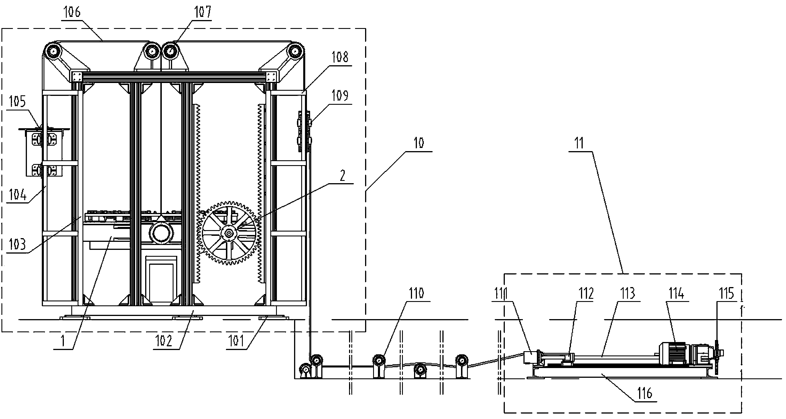
[0025] To measure the wave direction is to use the wave height tilt sensor and the azimuth sensor above it to measure the wave direction parameters. When the buoy tilts with the wave surface, the pendulum keeps a "vertical state" around its center of gravity, and the pendulum axis rotates clockwise or counterclockwise at different angles of the pendulum. By measuring the size and direction of the rotation angle of the pendulum axis, two sets of parameters of the pitch and heel of the buoy along with the wave surface can be obtained. Using these two sets of parameters, the azimuth of the buoy's inclination can be calculated, and this azimuth also reflects the direction of the wave surface inclination. However, the tilt direction of the wave surface calculated by measuring the rotation angle and direction of the pendulum shaft is relative to the direction of the baseline measured by the tilt sensor itself. This relative direction is corrected by the buoy azimuth measured by the ...


PUM


Abstract

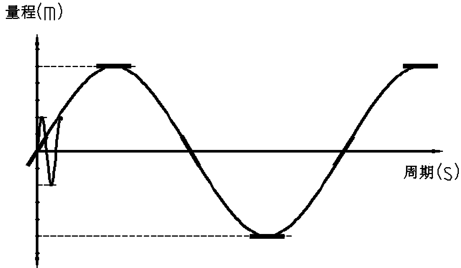
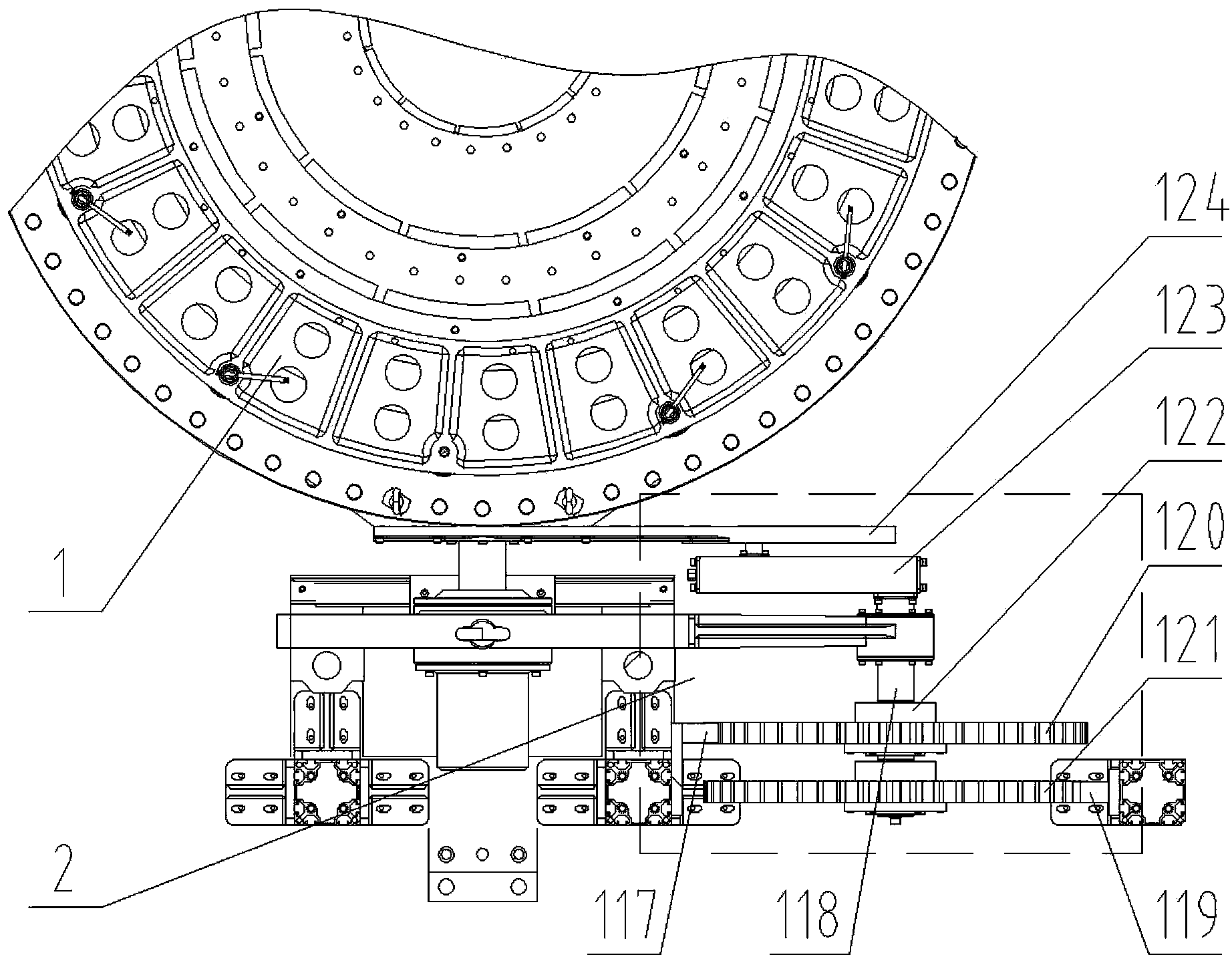
The invention discloses a wave direction detection device of a wave buoy. The wave direction detection device comprises a wave direction detection mechanism, a drive device, a controller device and a terminal control device, wherein a horizontal shaking mechanism comprises a main shaft, a first gear, a second gear, a slider-crank mechanism and an oscillating bar; the first gear and the second gear are coaxially installed on the main shaft, the horizontal shaking mechanism drives the oscillating bar through the slider-crank mechanism so as to drive a three-dimensional carrying rotating platform to swing. By adopting the wave direction detection device, the domestic blank of the test method and equipment for detecting the wave direction parameters of the wave buoy and a gravity acceleration sensor can be filled. Compared with the existing perpendicular lifting sinusoidal simulation and correction device established by National Oceanic and Atmospheric Administration (NOAA) in USA, the wave direction detection device has the advantages that by virtue of ingenuous design, the left-right swinging of the three-dimensional carrying rotating platform in the lifting reciprocating motion process can be realized by innovatively adopting two unidirectional overrunning clutch devices, so that the perpendicular lifting sinusoidal motion is closer to the real motion law of the wave, and the structural design is simple.

Description

technical field [0001] The invention relates to the technical field of ocean wave buoy measurement verification, in particular to a wave direction verification device for wave buoys, which is used for measurement verification of the wave direction of various wave buoys or gravity acceleration sensors, out of the ocean environment, and statically simulates the ocean A device with regular sinusoidal motion of waves. Background technique [0002] Wave is one of the six elements of marine hydrological observation, and also one of the important forms of motion of seawater. The gravity acceleration wave buoy is one of the most widely used wave buoys at present. With the continuous development of marine technology, countries have higher and higher requirements for the accuracy of wave buoys. Most of the existing verification and calibration devices that have been developed can only verify whether the buoy is working or not, and the calibration of the two parameters of wave height ...

Claims


Application Information

Patent Timeline
Patent Type & Authority Applications(China)
IPC IPC(8): G01C25/00
CPCG01C25/00
Inventor 朱飞徐喜东谢向前施春荣薛宜童
Owner 中船鹏力(南京)大气海洋信息系统有限公司
Learn More