Removable light switch

A lamp head switch and lamp head technology, which is applied to lighting devices, light sources, components of lighting devices, etc., can solve the problems of increased cost, large power supply, complicated detection, etc., and can improve production efficiency, improve safety, and reduce costs. Effect

Active Publication Date: 2017-11-14
SHANGHAI XINFENG ELECTRONICS
View PDF7 Cites 0 Cited by
  • Summary
  • Abstract
  • Description
  • Claims
  • Application Information

AI Technical Summary

Problems solved by technology

[0007] The invention discloses a removable lamp head switch, which is used to solve the problems of large power supply, increased cost and complicated detection caused by the scheme of adding a circuit on the power supply to control the leakage current of the lamp head in the prior art

Method used


Image

  • Removable light switch
  • Removable light switch
  • Removable light switch

Examples


Embodiment Construction

[0026] The present invention will be further described below in conjunction with the drawings and embodiments:

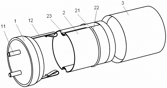
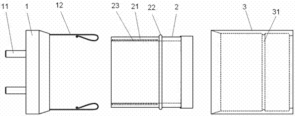
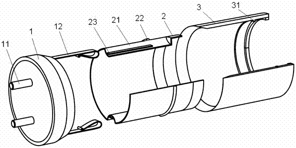
[0027] figure 1 It is a schematic diagram of the structure of the removable lamp holder switch of the present invention, figure 2 Is a cross-sectional view of the planar structure of the removable lamp holder switch of the present invention, image 3 Is a cross-sectional view of the three-dimensional structure of the removable lamp holder switch of the present invention, Figure 4 It is a schematic diagram of the structure of the installation lamp tube of the removable lamp holder switch of the present invention, please refer to Figure 1~Figure 4 , A removable lamp holder switch, which includes: a lamp holder 1, a pin 11 is installed on one surface of the lamp holder 1, and a sleeve 3 is further included, and the sleeve 3 is vertically installed on the other surface of the lamp holder 1. , The other surface of the lamp cap 1 is also vertically installed with two symme...


PUM


Abstract

The invention discloses a removable lamp head switch, which relates to the field of LED technology. On the other surface of the lamp cap, two symmetrical movable contact pieces are also vertically installed on the other surface of the lamp cap; an inner tube is placed in the sleeve, and the outer wall of the inner tube has two symmetrical and along the inner tube. The grooves are opened in the direction, and the contacts of the two movable contact pieces are respectively in contact with the bottoms of the two grooves; the two grooves are provided with static contact pieces, and the two static contact pieces are both arranged on the bottom of the two grooves. The side of the contact point of the movable contact piece and the contact point of the groove close to the lamp head, the static contact piece and the contact point of the movable contact piece are not in contact. The structure of the present invention avoids the potential electric shock caused by the operator touching the pins during the installation process, and has high safety. The present invention has a simple structure, does not need manual testing, and reduces costs while improving production efficiency.

Description

Technical field [0001] The invention relates to an LED technology, in particular to a removable lamp holder switch. Background technique [0002] Due to the particularity of the power supply method and installation method of the double-ended LED fluorescent tube, if the operator holds one end and connects the other end to the electrode, there is a possibility of electric shock and the operator has a safety hazard. [0003] The solutions in the prior art mostly adopt adding circuits to the power supply to reduce leakage current, but this technical solution has the following defects: [0004] 1. The circuit is too complicated, resulting in a large power supply; [0005] 2. Increasing the circuit will increase the cost; [0006] 3. The detection method is more complicated. The corresponding lamp holder needs to be made. The lamp holder is removed from one end of the lamp holder, and a non-inductive 500Ω resistor is connected between a touchable pin and the ground, and then the resistance ...

Claims


Application Information

Patent Timeline
Patent Type & Authority Patents(China)
IPC IPC(8): F21V23/04F21K9/278F21Y115/10
Inventor 李永顺常慧卡陈桂花
Owner SHANGHAI XINFENG ELECTRONICS
Why Eureka
Try Eureka